
Guide


Thermal and Mechanical Design
60 Intel® Xeon® Processor E7 2800/4800/8800 v2 Product Family
Thermal/ Mechanical Specifications and Design Guide
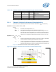
2.5.3 Tower Heatsink Performance
Figure 2-31 shows thermal resistance (Ψ
CA
) and pressure drop (ΔP) for the 4U heatsink
versus the airflow. Best-fit equations are provided to prevent errors associated with
reading the graph.
• ΔP = (2.106 x 10
-05
) * CFM
2
+ (5.51 x 10
-03
) * CFM
• Ψ
CA
= 0.1292 + 1.35*CFM
-0.9637
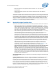
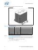
Figure 2-30. Processor Reference Heatsink Isometric View
Table 2-20. Tower Heatsink Design
Parameter Value Notes
Heatsink technology Cu/Al base / Al fins /
heatpipes
Heatpipe Quantity 4
TIM Size 35 x 35 mm
Fin Quantity See heatsink drawing in Appendix G
Fin Size See heatsink drawing in Appendix G
Weight ~580g
Fin Support Mechanism Yes See heatsink drawing in Appendix G