
Guide


Thermal and Mechanical Design
Intel® Xeon® Processor E7 2800/4800/8800 v2 Product Family 53
Thermal/ Mechanical Specifications and Design Guide
• Determine whether that optimized thermal solution can meet processor
specifications
• Iterate through the previous steps to find a solution that will meet thermal
requirements
To develop a reliable and cost-effective thermal solution, thermal characterization and
simulation should be carried out at the entire system level, accounting for the thermal
requirements of each component. In addition, acoustic noise constraints may limit the
size, number, placement, and types of air-movers that can be used in a particular
design. A number of collaterals, such as thermal and mechanical models, are made
available to aid in performing system and component level thermal characterizations.
See Section 1.3 for the listing of available collaterals.
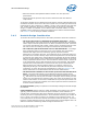
2.4.2 Heatsink Design Consideration
To remove the heat from the processor, three basic parameters should be considered:
• The area of the surface on which the heat transfer takes place – Without
any enhancements, this is the surface of the processor package IHS. One method
used to improve thermal performance is to attach a heatsink to the IHS. A heatsink
can increase the effective heat transfer surface area by conducting heat out of the
IHS and into the surrounding air through fins attached to the heatsink base.
• The conduction path from the heat source to the heatsink fins – Providing a
direct conduction path from the heat source to the heatsink fins and selecting
materials with higher thermal conductivity typically improves heatsink
performance. The length, thickness, and conductivity of the conduction path from
the heat source to the fins directly impact the thermal performance of the heatsink.
In particular, the quality of the contact between the package IHS and the heatsink
base has a higher impact on the overall thermal solution performance as processor
cooling requirements become strict. Thermal interface material (TIM) is used to fill
in the gap between the IHS and the bottom surface of the heatsink, and thereby
improves the overall performance of the thermal stack-up (IHS-TIM-Heatsink).
With extremely poor heatsink interface flatness or roughness, TIM may not
adequately fill the gap. The TIM thermal performance depends on its thermal
conductivity as well as the pressure load applied to it. Refer to Section 2.2.6 for
further information on the TIM between the IHS and the heatsink base.
• The heat transfer conditions on the surface upon which heat transfer takes
place – Convective heat transfer occurs between the airflow and the surface
exposed to the flow. It is characterized by the local ambient temperature of the air,
T
LA
, and the local air velocity over the surface. The higher the air velocity over the
surface, the more efficient the resulting cooling. The nature of the airflow can also
enhance heat transfer via convection. Turbulent flow can provide improvement over
laminar flow. In the case of a heatsink, the surface exposed to the flow includes the
fin faces and the heatsink base.
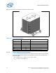
An active heatsink typically incorporates a fan that helps manage the airflow through
the heatsink.
Passive heatsink solutions require in-depth knowledge of the airflow in the chassis.
Typically, passive heatsinks see slower air speed. Therefore, these heatsinks are
typically larger (and heavier) than active heatsinks due to the increase in fin surface
necessary to meet a required performance. As the heatsink fin density (the number of
fins in a given cross-section) increases, the resistance to the airflow increases; it is
more likely that the air will travel around the heatsink instead of through it, unless air
bypass is carefully managed. Using air-ducting techniques to manage bypass area is an
effective method for maximizing airflow through the heatsink fins.