
Guide


Thermal and Mechanical Design
Intel® Xeon® Processor E7 2800/4800/8800 v2 Product Family 35
Thermal/ Mechanical Specifications and Design Guide
2.1.5.3 ILM Back Plate Design Overview
The backplate assembly consists of a supporting plate and captive standoffs. It
provides rigidity to the system to ensure minimal board and socket deflection. Four
externally threaded (male) inserts which are press fit into the backplate are for ILM
attachment. Three cavities are located at the center of the plate to allow access to the
baseboard test points and backside capacitors. An insulator is pre-applied to prevent
shorting the board.
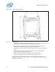
Figure 2-18. ILM Keying
ILM-Socket Keying
Table 2-8. ILM Back Plate Design Criteria
Parameter Value Note
Material thickness 2.2 ± 0.05 mm To meet the PCB secondary side
clearance requirement
Does not include insulator thickness.
Insulator thickness 0.178 mm min See insulator drawing for details
Material strength Yield 250 MPa min
Ultimate 300 MPa min
Flatness 0.2mm
PEM Insert Push-out Force 1110 N
PEM Insert Torque Out 1.4 N-m
Outside perimeter 90 x 78 mm min Customizing beyond this perimeter of
back plate should meet the reliability
objectives.
Cavity (3x) Center: 24.4 x 16 mm
Sides (2x): 25.4 x 7 mm
See back plate mechanical drawings
for details