
Nettop Platform for 2008 System Design White Paper


Improving System Thermal Performance
White Paper 25
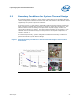
5.2 Boundary Conditions for System Thermal Design
By analyzing airflow condition in μATX chassis, airflow data across multiples different
chassis configuration indicates the actual test data and statistic of the effective airflow
supplied by the system to processor heatsink.
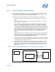
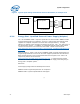
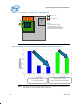
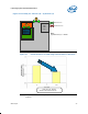
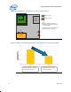
As shown in
Figure 7, high airflow (>200LFM) could be achieved if power supply unit
(PSU) with fan is located near processor as shown by chassis B in the
Figure 7. The
effective airflow varies according to the placement of power supply unit fan and
system fan locations in a chassis. The lowest observed airflow in the system is <50
LFM with the fan located far away from the processor and chipset components, as
shown in chassis A.
As mentioned previously, system configurations determine boundary condition for
passive and fanless system thermal design.
Figure 7 Airflow Boundary Conditions for Passive Heatsink Design in Various Micro
ATX Chassis
A
B
Fanless
- Chassis Ventilation
-
La
y
out
System Fan
- Fan location
PSU Fan
- Fan location
B
A