
Nettop Platform for 2008 System Design White Paper


4 White Paper
Figures
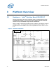
Figure 1 Platform Configuration .......................................................................10
Figure 2 Major components on board................................................................12
Figure 3 S-Video Connections..........................................................................17
Figure 4 S-Video Pin Definitions.......................................................................18
Figure 5 Typical Input Voltage of the DC-DC board in the Market,
for example 12 V ..............................................................................
21
Figure 6 Typical Input Voltage of the DC-DC Board in the Market,
for example 19 V .............................................................................
22
Figure 7 Airflow Boundary Conditions for Passive Heatsink Design in Various
Micro ATX Chassis............................................................................
25
Figure 8 Schematic of Typical Micro ATX System Placement................................26
Figure 9 Case study #1: PSU Fan (A) + System Fan (B)....................................28
Figure 10 Results of Two Chassis Tested Using Same Heatsink on Processor ...........28
Figure 11 Case Study #2: PSU Fan (A) + System Fan (C) ...................................29
Figure 12 Results Chassis #3 Tested Using Same Heatsink on Processor ................29
Figure 13 Case Study #3: System Fan (D) versus System Fan (F)........................30
Figure 14 I mpact of System Fan Placement on the Airflow Over Processor Heatsink 30
Figure 15 0° Angle Attach Methodology (top view, not to scale) ............................37
Figure 16 0° Angle Attach Heatsink Modifications (generic heatsink side and
bottom view, not to scale).................................................................
38
Tables
Table 1 Platform Features................................................................................9
Table 2 Platform Features Summary................................................................11
Table 3 Items in Figure 2...............................................................................12
Table 4 Drivers and Software for Devices.........................................................14
Table 5 System Components List....................................................................16
Table 6 Video Specifications...........................................................................18
Table 7 Typical Power Distribution ..................................................................19
Table 8 Summary of Case Studies...................................................................32
Table 9 Shock Parameters .............................................................................40
Table 10 Vibration Parameters .........................................................................41