
Nettop Platform for 2008 System Design White Paper
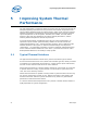

Improving System Thermal Performance
White Paper 27
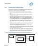
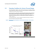
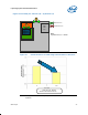
5.3.1 Case Study #1
Case study #1 shows the impact of PSU fan (A) and system fan (B) placements at
back panel on the thermal boundary conditions, as shown in
Figure 9.
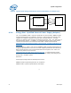
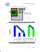
The results of two chassis tested using a same heatsink on processor is shown in
Figure 10. Y-axis is normalized specification with 1.0 is value as processor passing
thermal requirement.
In chassis #1, system back-panel fan (B) is just good enough to provide boundary
condition passing the thermal requirement. If a PSU fan of 80mm is properly aligned
with processor heatsink, an improvement of over 50% in airflow boundary condition
has been observed over processor heatsink. As a result, a further cost reduction in
processor heatsink design with possible smaller and lighter heatsink design can be
implemented. Hence, a combination of system & PSU fan will provide enhanced
boundary condition.
In chassis #2, test data shows the importance of PSU fan size and its relative location
to processor heatsink. A 30mm offset PSU fan (60mm size) will degrade boundary
condition by almost 100%. Again, boundary condition could be further enhanced with
system fan (B) added.
The two tested chassis configurations in Case Study #1 conclude that a PSU fan aligns
with heatsink will provide good airflow (100~130LFM range) to processor heatsink,
and meanwhile exhausting hot air away from system. Adding a system fan at back-
panel of chassis will further enhance the boundary condition in a chassis.
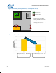
5.3.2 Case Study #2
Case study #2 in Figure 11 and Figure 12 shows that adding a system fan (C) can
further improve airflow conditions in chassis. Comparing chassis#2 (in
Figure 10) and
chassis #3 (in
Figure 12) results, system fan is preferably to be located at the top side
of the chassis to provide efficient airflow over processor heatsink.
5.3.3 Case Study #3
Case study#3 is a typical example showing the impact of airflow with inefficient fan
locations at (D) and (E). Even if chassis #4 is equipped with an inlet system fan (D)
(at front panel) and a PSU fan (E), the result in
Figure 14 shows that it is not providing an effective airflow boundary condition to cool
components on motherboard.
Figure 14 shows that the airflow condition provided by fan (D) and fan (E) does not
meet thermal requirement. Relocating system fan (D) to location (F) by mounting the
fan onto existing side vent of chassis wall can significantly improve airflow condition
by around 50% by supplying impingement airflow to processor heatsink.