Intel® Desktop Board DX48BT2 Technical Product Specification March 2008 Order Number: E29116-001US The Intel® Desktop Board DX48BT2 may contain design defects or errors known as errata that may cause the product to deviate from published specifications. Current characterized errata are documented in the Intel Desktop Board DX48BT2 Specification Update.
Revision History Revision -001 Revision History Date ® First release of the Intel Desktop Board DX48BT2 Technical Product Specification March 2008 This product specification applies to only the standard Intel® Desktop Board DX48BT2 with BIOS identifier BTX3810J.86A. Changes to this specification will be published in the Intel Desktop Board DX48BT2 Specification Update before being incorporated into a revision of this document. INFORMATION IN THIS DOCUMENT IS PROVIDED IN CONNECTION WITH INTEL® PRODUCTS.
Preface This Technical Product Specification (TPS) specifies the board layout, components, connectors, power and environmental requirements, and the BIOS for the Intel® Desktop Board DX48BT2. Intended Audience The TPS is intended to provide detailed, technical information about the Intel Desktop Board DX48BT2 and its components to the vendors, system integrators, and other engineers and technicians who need this level of information. It is specifically not intended for general audiences.
Intel Desktop Board DX48BT2 Technical Product Specification Other Common Notation iv # Used after a signal name to identify an active-low signal (such as USBP0#) GB Gigabyte (1,073,741,824 bytes) GB/sec Gigabytes per second Gbits/sec Gigabits per second KB Kilobyte (1024 bytes) Kbit Kilobit (1024 bits) kbits/sec 1000 bits per second MB Megabyte (1,048,576 bytes) MB/sec Megabytes per second Mbit Megabit (1,048,576 bits) Mbits/sec Megabits per second xxh An address or data value endi
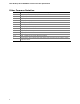
Contents 1 Product Description 1.1 Overview........................................................................................ 10 1.1.1 Feature Summary ................................................................ 10 1.1.2 Board Layout ....................................................................... 12 1.1.3 Block Diagram ..................................................................... 14 1.2 Legacy Considerations......................................................................
Intel Desktop Board DX48BT2 Technical Product Specification 2.2 Connectors and Headers................................................................... 43 2.2.1 Back Panel Connectors .......................................................... 44 2.2.2 Component-side Connectors and Headers ................................ 45 2.3 Jumper Block .................................................................................. 55 2.4 Mechanical Considerations ...................................................
Contents 5 Regulatory Compliance and Battery Disposal Information 5.1 Regulatory Compliance..................................................................... 5.1.1 Safety Standards.................................................................. 5.1.2 European Union Declaration of Conformity Statement ................ 5.1.3 Product Ecology Statements................................................... 5.1.4 EMC Regulations .................................................................. 5.1.
Intel Desktop Board DX48BT2 Technical Product Specification 17. 18. 19. 20. 21. 22. 23. 24. 25. 26. 27. 28. 29. 30. 31. 32. 33. 34. 35. 36. 37. 38. 39. 40. 41. viii Processor Core Power Connector........................................................ Main Power Connector...................................................................... Auxiliary PCI Express Graphics Power ................................................. Front Panel Header ............................................................
1 Product Description What This Chapter Contains 1.1 Overview........................................................................................ 10 1.2 Legacy Considerations...................................................................... 15 1.3 Online Support................................................................................ 15 1.4 Processor ....................................................................................... 15 1.5 System Memory .................................
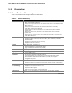
Intel Desktop Board DX48BT2 Technical Product Specification 1.1 Overview 1.1.1 Feature Summary Table 1 summarizes the major features of the board. Table 1. Feature Summary Form Factor ATX (12.00 inches by 9.60 inches [304.80 millimeters by 243.
Product Description Table 1. Feature Summary (continued) Expansion Capabilities • Two PCI* Conventional bus add-in card connectors (SMBus routed to both PCI Conventional bus add-in card connectors) • Two PCI Express 2.0 x16 bus add-in card connectors • One PCI Express 1.
Intel Desktop Board DX48BT2 Technical Product Specification 1.1.2 Board Layout Figure 1 shows the location of the major components on board DX48BT2. Figure 1. Major Board Components Table 2 lists the components identified in Figure 1.
Product Description Table 2.
Intel Desktop Board DX48BT2 Technical Product Specification 1.1.3 Block Diagram Figure 2 is a block diagram of the major functional areas of the board DX48BT2. Figure 2.
Product Description 1.2 Legacy Considerations This board differs from other Intel Desktop Board products, with specific changes including (but not limited to) the following: • • • • • 1.3 No No No No No parallel port floppy drive connector serial port PCI Express X1 connector PS/2 connectors Online Support To find information about… Visit this World Wide Web site: Intel® Desktop Board DX48BT2 http://www.intel.com/products/motherboard/DX48BT2/index.htm Desktop Board Support http://support.intel.
Intel Desktop Board DX48BT2 Technical Product Specification CAUTION Use only the processors listed on the web site above. Use of unsupported processors can damage the board, the processor, and the power supply. # INTEGRATOR’S NOTE This board has specific requirements for providing power to the processor. Refer to Section 2.5.1 on page 57 for information on power supply requirements for this board. 1.
Product Description Table 3 lists the supported DIMM configurations. Table 3.
Intel Desktop Board DX48BT2 Technical Product Specification Figure 3 illustrates the memory channel and DIMM configuration. NOTE The DIMM 0 sockets of both channels are blue. The DIMM 1 sockets of both channels are black. Figure 3.
Product Description Intel® X48 Chipset 1.6 The Intel X48 chipset consists of the following devices: • • Intel 82X48 Memory Controller Hub (MCH) with Direct Media Interface (DMI) interconnect Intel 82801IR I/O Controller Hub (ICH9R) The MCH component provides interfaces to the processor, memory, and PCI Express. The ICH9R is a centralized controller for the board’s I/O paths. For information about Refer to The Intel X48 chipset http://www.intel.com/products/desktop/chipsets/index.
Intel Desktop Board DX48BT2 Technical Product Specification 1.6.2 Serial ATA Interfaces The board provides six Serial ATA (SATA) connectors, which support one device per connector. The board also provides two red-colored external Serial ATA (eSATA) connectors on the back panel. 1.6.2.1 Serial ATA Support The board’s Serial ATA controller offers six independent Serial ATA ports with a theoretical maximum transfer rate of 3 Gbits/sec per port.
Product Description 1.7 Discrete eSATA/PATA Controller The board provides a discrete Marvell* controller to support two eSATA connectors on the back panel and one PATA connector. 1.7.1 External Serial ATA Support The red Serial ATA connectors on the back panel can be used for an external SATA drive. They can also be used for port replication, which allows the aggregation of multiple hard drives on each of the eSATA ports.
Intel Desktop Board DX48BT2 Technical Product Specification NOTE ATA-66 and ATA-100 are faster timings and require an 80-pin conductor cable to reduce reflections, noise, and inductive coupling. The Parallel ATA IDE interface also supports ATAPI devices (such as CD-ROM drives) and ATA devices. The BIOS supports Logical Block Addressing (LBA) and Extended Cylinder Head Sector (ECHS) translation modes. The drive reports the transfer rate and translation mode to the BIOS. 1.
Product Description 1.9 Legacy I/O Controller The I/O controller provides the following features: • • • • Consumer Infrared (CIR) headers Serial IRQ interface compatible with serialized IRQ support for PCI systems Intelligent power management, including a programmable wake-up event interface PCI power management support The BIOS Setup program provides configuration options for the I/O controller. 1.9.
Intel Desktop Board DX48BT2 Technical Product Specification 1.10 Audio Subsystem The board supports the Intel High Definition audio subsystem based on the IDT STAC9274D audio codec. The audio subsystem supports the following features: • • • • Advanced jack sense for the back panel audio jacks that enables the audio codec to recognize the device that is connected to an audio port.
Product Description 1.10.3 8-Channel (7.1) Audio Subsystem The 8-channel (7.1) audio subsystem includes the following: • • • Intel 82801IR (ICH9R) IDT STAC9274D audio codec Microphone input that supports a single dynamic, condenser, or electret microphone The back panel audio connectors are configurable through the audio device drivers. The available configurable audio ports are shown in Figure 4.
Intel Desktop Board DX48BT2 Technical Product Specification 1.
Product Description 1.11.2 LAN Subsystem Software LAN software and drivers are available from Intel’s World Wide Web site. For information about Refer to Obtaining LAN software and drivers http://downloadcenter.intel.com 1.11.3 RJ-45 LAN Connector with Integrated LEDs Two LEDs are built into the RJ-45 LAN connector (shown in Figure 5 below). Item Description A Link LED (Green) B Data Rate LED (Green/Yellow) Figure 5.
Intel Desktop Board DX48BT2 Technical Product Specification 1.11.
Product Description 1.12 Hardware Management Subsystem The hardware management features enable the board to be compatible with the Wired for Management (WfM) specification. The board has several hardware management features, including the following: • • • Fan monitoring and control Thermal and voltage monitoring Chassis intrusion detection 1.12.
Intel Desktop Board DX48BT2 Technical Product Specification 1.12.4 Thermal Monitoring Figure 6 shows the locations of the thermal sensors and fan headers. Item Description A Auxiliary rear chassis fan B Rear chassis fan C MCH fan D Thermal diode, located on processor die E Processor fan F Front chassis fan G Thermal diode, located on the MCH die H Thermal diode, located on the ICH9R die Figure 6.
Product Description 1.13 Power Management Power management is implemented at several levels, including: • • Software support through Advanced Configuration and Power Interface (ACPI) Hardware support: ⎯ Power connector ⎯ Fan headers ⎯ LAN wake capabilities ⎯ Instantly Available PC technology ⎯ Wake from USB ⎯ Power Management Event signal (PME#) wake-up support ⎯ PCI Express WAKE# signal support 1.13.
Intel Desktop Board DX48BT2 Technical Product Specification Table 5 lists the system states based on how long the power switch is pressed, depending on how ACPI is configured with an ACPI-aware operating system. Table 5.
Product Description Table 6 lists the power states supported by the board along with the associated system power targets. See the ACPI specification for a complete description of the various system and power states. Table 6. Power States and Targeted System Power Processor Targeted System Power (Note 1) Global States Sleeping States States Device States G0 – working state S0 – working C0 – working D0 – working state.
Intel Desktop Board DX48BT2 Technical Product Specification 1.13.1.2 ENERGY STAR* In 2007, the US Department of Energy and the US Environmental Protection Agency revised the ENERGY STAR* requirements. Intel has worked directly with these two governmental agencies to define the new requirements. Currently this Intel Desktop Board meets the new Category C requirements. For information about Refer to ENERGY STAR requirements and recommended configurations http://www.intel.com/go/energystar 1.13.1.
Product Description 1.13.2 Hardware Support CAUTION Ensure that the power supply provides adequate +5 V standby current if LAN wake capabilities and Instantly Available PC technology features are used. Failure to do so can damage the power supply. The total amount of standby current required depends on the wake devices supported and manufacturing options.
Intel Desktop Board DX48BT2 Technical Product Specification 1.13.2.2 Fan Headers The function/operation of the fan headers is as follows: • • • • • • • The fans are on when the board is in the S0 or S1 state. The fans are off when the board is off or in the S3, S4, or S5 state.
Product Description 1.13.2.4 Instantly Available PC Technology CAUTION For Instantly Available PC technology, the +5 V standby line for the power supply must be capable of providing adequate +5 V standby current. Failure to provide adequate standby current when implementing Instantly Available PC technology can damage the power supply. Instantly Available PC technology enables the board to enter the ACPI S3 (Suspend-toRAM) sleep-state.
Intel Desktop Board DX48BT2 Technical Product Specification 1.13.2.8 +5 V Standby Power Indicator LED and Additional LEDs The +5 V standby power indicator LED shows that power is still present even when the computer appears to be off. Figure 7 shows the location of the standby power indicator LED on the board. CAUTION If AC power has been switched off and the standby power indicators are still lit, disconnect the power cord before installing or removing any devices connected to the board.
Product Description 1.14 Onboard Power Button The board provides a power button that can be used to turn the computer on or off. This button is intended for use at integration facilities to remove standby power before making changes to the system configuration, or for testing purposes. The power button on the front panel is recommended for all other instances of turning the computer on or off. To turn the computer off using the onboard power button, keep the button pressed down for three seconds.
Intel Desktop Board DX48BT2 Technical Product Specification 40
2 Technical Reference What This Chapter Contains 2.1 2.2 2.3 2.4 2.5 2.6 2.7 2.8 2.1 2.1.1 Memory Resources .......................................................................... 41 Connectors and Headers................................................................... 43 Jumper Block .................................................................................. 55 Mechanical Considerations ................................................................ 56 Electrical Considerations ..........
Intel Desktop Board DX48BT2 Technical Product Specification 8 GB Top of System Address Space Upper 4 GB of address space FLASH APIC ~20 MB Reserved PCI Memory Range contains PCI, chipsets, Direct Media Interface (DMI), and ICH ranges (approximately 750 MB) 0FFFFFH 0F0000H 0EFFFFH Top of usable DRAM (memory visible to the operating system) 0E0000H 0DFFFFH 0C0000H DRAM Range 0BFFFFH 1 MB DOS Compatibility Memory 640 KB 0A0000H 1 MB Upper BIOS area (64 KB) 960 KB Lower BIOS area (64 KB; 16 KB x 4)
Technical Reference 2.1.2 Memory Map Table 8 lists the system memory map. Table 8. System Memory Map Address Range (decimal) Address Range (hex) Size Description 1024 K - 8388608 K 100000 - 1FFFFFFFF 8191 MB Extended memory 960 K - 1024 K F0000 - FFFFF 64 KB Runtime BIOS 896 K - 960 K E0000 - EFFFF 64 KB Reserved 800 K - 896 K C8000 - DFFFF 96 KB Potential available high DOS memory (open to the PCI Conventional bus). Dependent on video adapter used.
Intel Desktop Board DX48BT2 Technical Product Specification 2.2.1 Back Panel Connectors Figure 10 shows the location of the back panel connectors for the DX48BT2 board equipped with the 8-channel (7.1) audio subsystem.
Technical Reference 2.2.2 Component-side Connectors and Headers Figure 11 shows the locations of the component-side connectors and headers. Figure 11. Component-side Connectors and Headers Table 9 lists the component-side connectors and headers identified in Figure 11.
Intel Desktop Board DX48BT2 Technical Product Specification Table 9.
Technical Reference 2.2.2.1 Signal Tables for the Connectors and Headers Table 10. HD Audio Link Header Pin Signal Name Pin Signal Name 1 BCLK 2 Ground 3 RST# 4 3.3 VCC 5 SYNC 6 Ground 7 SDO 8 3.3 VCC 9 SDI0 10 +12 V 11 SDI1 12 Key (no pin) 13 Aud RSVD 14 3.3 V STBY 15 Aud RSVD 16 Ground Table 11.
Intel Desktop Board DX48BT2 Technical Product Specification Table 13. Chassis Intrusion Header Pin Signal Name 1 Intruder 2 Ground Table 14. Front and Rear Chassis (3-Pin) Fan Headers Pin Signal Name 1 Control (Note) 2 +12 V 3 Note: Tach These fan headers use voltage variance control for fan speed. Table 15.
Technical Reference 2.2.2.2 Add-in Card Connectors The board has the following add-in card connectors: • • • PCI Express 2.0 x16: two PCI Express 2.0 x16 connectors supporting simultaneous transfer speeds up to 8 GB/sec of peak bandwidth per direction and up to 16 GB/sec concurrent bandwidth. PCI Express 1.1 x4: one PCI Express 1.1 x4 connector (implemented using a x16 physical connector).
Intel Desktop Board DX48BT2 Technical Product Specification 2.2.2.4 Power Supply Connectors The board has the following power supply connectors: • • • Main power – a 2 x 12 connector. This connector is compatible with 2 x 10 connectors previously used on Intel Desktop boards. The board supports the use of ATX12V power supplies with either 2 x 10 or 2 x 12 main power cables.
Technical Reference Table 18. Main Power Connector Pin Signal Name Pin Signal Name 1 +3.3 V 13 +3.3 V 2 +3.
Intel Desktop Board DX48BT2 Technical Product Specification 2.2.2.5 Front Panel Header This section describes the functions of the front panel header. Table 20 lists the signal names of the front panel header. Figure 12 is a connection diagram for the front panel header. Table 20.
Technical Reference 2.2.2.5.2 Reset Switch Header Pins 5 and 7 can be connected to a momentary single pole, single throw (SPST) type switch that is normally open. When the switch is closed, the board resets and runs the POST. 2.2.2.5.3 Power/Sleep LED Header Pins 2 and 4 can be connected to a one- or two-color LED. Table 21 shows the possible states for a one-color LED. Table 22 shows the possible states for a two-color LED. Table 21.
Intel Desktop Board DX48BT2 Technical Product Specification 2.2.2.6 Front Panel USB Headers Figure 13 is a connection diagram for the front panel USB headers. # INTEGRATOR’S NOTES • • The +5 V DC power on the USB headers is fused. Use only a front panel USB connector that conforms to the USB 2.0 specification for high-speed USB devices. Figure 13. Connection Diagram for Front Panel USB Headers 2.2.2.7 Front Panel IEEE 1394a Header Figure 14 is a connection diagram for the IEEE 1394a header.
Technical Reference 2.3 Jumper Block CAUTION Do not move the jumper with the power on. Always turn off the power and unplug the power cord from the computer before changing a jumper setting. Otherwise, the board could be damaged. Figure 15 shows the location of the jumper block. The 3-pin jumper block determines the BIOS Setup program’s mode. Table 23 describes the jumper settings for the three modes: normal, configure, and recovery.
Intel Desktop Board DX48BT2 Technical Product Specification 2.4 2.4.1 Mechanical Considerations Form Factor The board is designed to fit into an ATX-form-factor chassis. Figure 16 illustrates the mechanical form factor for the board. Dimensions are given in inches [millimeters]. The outer dimensions are 12.00 inches by 9.60 inches [304.80 millimeters by 243.84 millimeters]. Location of the I/O connectors and mounting holes are in compliance with the ATX specification. Figure 16.
Technical Reference 2.5 Electrical Considerations 2.5.1 Power Supply Considerations CAUTION The +5 V standby line from the power supply must be capable of providing adequate +5 V standby current. Failure to do so can damage the power supply. The total amount of standby current required depends on the wake devices supported and manufacturing options. Additional power required will depend on configurations chosen by the integrator.
Intel Desktop Board DX48BT2 Technical Product Specification 2.5.2 Fan Header Current Capability CAUTION The processor fan must be connected to the processor fan header, not to a chassis fan header. Connecting the processor fan to a chassis fan header may result in onboard component damage that will halt fan operation. Table 25 lists the current capability of the fan headers. Table 25. Fan Header Current Capability Fan Header Maximum Available Current Processor fan 2.0 A Front chassis fan 1.
Technical Reference CAUTION Ensure that the ambient temperature does not exceed the board’s maximum operating temperature. Failure to do so could cause components to exceed their maximum case temperature and malfunction. For information about the maximum operating temperature, see the environmental specifications in Section 2.8. CAUTION Ensure that proper airflow is maintained in the processor voltage regulator circuit. Failure to do so may result in damage to the voltage regulator circuit.
Intel Desktop Board DX48BT2 Technical Product Specification Table 26 provides maximum case temperatures for the components that are sensitive to thermal changes. The operating temperature, current load, or operating frequency could affect case temperatures. Maximum case temperatures are important when considering proper airflow to cool the board. Table 26.
Technical Reference 2.7 Reliability The Mean Time Between Failures (MTBF) prediction is calculated using component and subassembly random failure rates. The calculation is based on the Bellcore Reliability Prediction Procedure, TR-NWT-000332, Issue 4, September 1991. The MTBF prediction is used to estimate repair rates and spare parts requirements. The MTBF data is calculated from predicted data at 55 ºC. The MTBF for the board is 81,737 hours. 2.
Intel Desktop Board DX48BT2 Technical Product Specification 62
3 Overview of BIOS Features What This Chapter Contains 3.1 Introduction ................................................................................... 3.2 BIOS Flash Memory Organization ....................................................... 3.3 Resource Configuration .................................................................... 3.4 System Management BIOS (SMBIOS)................................................. 3.5 Legacy USB Support ...........................................................
Intel Desktop Board DX48BT2 Technical Product Specification Table 28 lists the BIOS Setup program menu features. Table 28.
Overview of BIOS Features 3.3.2 PCI IDE Support If you select IDE in the BIOS Setup program, the BIOS automatically sets up the PCI IDE connector with independent I/O channel support. The IDE interface supports hard drives up to ATA-66/100 and recognizes any ATAPI compliant devices, including CD-ROM drives, tape drives, and Ultra DMA drives. The BIOS determines the capabilities of each drive and configures them to optimize capacity and performance.
Intel Desktop Board DX48BT2 Technical Product Specification 3.5 Legacy USB Support Legacy USB support enables USB devices to be used even when the operating system’s USB drivers are not yet available. Legacy USB support is used to access the BIOS Setup program, and to install an operating system that supports USB. By default, Legacy USB support is set to Enabled. Legacy USB support operates as follows: 1. When you apply power to the computer, legacy support is disabled. 2. POST begins. 3.
Overview of BIOS Features 3.6 BIOS Updates The BIOS can be updated using either of the following utilities, which are available on the Intel World Wide Web site: • • Intel® Express BIOS Update utility, which enables automated updating while in the Windows environment. Using this utility, the BIOS can be updated from a file on a hard disk, a USB drive (a flash drive or a USB hard drive), or a CD-ROM, or from the file location on the Web.
Intel Desktop Board DX48BT2 Technical Product Specification 3.7 BIOS Recovery It is unlikely that anything will interrupt a BIOS update; however, if an interruption occurs, the BIOS could be damaged. Table 30 lists the drives and media types that can and cannot be used for BIOS recovery. The BIOS recovery media does not need to be made bootable. Table 30.
Overview of BIOS Features 3.8 Boot Options In the BIOS Setup program, the user can choose to boot from a diskette drive, hard drive, USB drive, USB flash drive, CD-ROM, or the network. The default setting is for the diskette drive to be the first boot device, the hard drive second, and the ATAPI CD-ROM third. If enabled, the last default boot device is the network. 3.8.1 CD-ROM Boot Booting from CD-ROM is supported in compliance to the El Torito bootable CD-ROM format specification.
Intel Desktop Board DX48BT2 Technical Product Specification 3.9 Adjusting Boot Speed These factors affect system boot speed: • • 3.9.1 Selecting and configuring peripherals properly Optimized BIOS boot parameters Peripheral Selection and Configuration The following techniques help improve system boot speed: • • • • 3.9.2 Choose a hard drive with parameters such as “power-up to data ready” less than eight seconds, that minimize hard drive startup delays.
Overview of BIOS Features 3.10 BIOS Security Features The BIOS includes security features that restrict access to the BIOS Setup program and who can boot the computer. A supervisor password and a user password can be set for the BIOS Setup program and for booting the computer, with the following restrictions: • • • • • • • The supervisor password gives unrestricted access to view and change all the Setup options in the BIOS Setup program. This is the supervisor mode.
Intel Desktop Board DX48BT2 Technical Product Specification 3.11 BIOS Performance Features The BIOS includes the following options to provide custom performance enhancements when using either Intel Core 2 Extreme processors and other Intel® processors. • • • • Processor frequency adjustment Processor voltage adjustment Memory clock adjustments Memory voltage adjustments NOTE The system will automatically set the memory frequency to match the processors’ front side bus frequency.
4 Error Messages and Beep Codes What This Chapter Contains 4.1 4.2 4.3 4.4 4.1 Speaker ......................................................................................... 73 BIOS Beep Codes ............................................................................ 73 BIOS Error Messages ....................................................................... 73 Port 80h POST Codes .......................................................................
Intel Desktop Board DX48BT2 Technical Product Specification 4.4 Port 80h POST Codes During the POST, the BIOS generates diagnostic progress codes (POST codes) to I/O port 80h. If the POST fails, execution stops and the last POST code generated is left at port 80h. This code is useful for determining the point where an error occurred. Displaying the POST codes requires a PCI bus add-in card, often called a POST card.
Error Messages and Beep Codes Table 36.
Intel Desktop Board DX48BT2 Technical Product Specification Table 36.
Error Messages and Beep Codes Table 36.
Intel Desktop Board DX48BT2 Technical Product Specification Table 37.
5 Regulatory Compliance and Battery Disposal Information What This Chapter Contains 5.1 Regulatory Compliance..................................................................... 79 5.2 Battery Disposal Information............................................................. 87 5.1 Regulatory Compliance This section contains the following regulatory compliance information for Desktop Board DX48BT2: • • • • • 5.1.
Intel Desktop Board DX48BT2 Technical Product Specification 5.1.2 European Union Declaration of Conformity Statement We, Intel Corporation, declare under our sole responsibility that the product Intel® Desktop Board DX48BT2 is in conformity with all applicable essential requirements necessary for CE marking, following the provisions of the European Council Directive 2004/108/EC (EMC Directive) and 2006/95/EC (Low Voltage Directive).
Regulatory Compliance and Battery Disposal Information Español Este producto cumple con las normas del Directivo Europeo 2004/108/EC & 2006/95/EC. Slovensky Tento produkt je v súlade s ustanoveniami európskych direktív 2004/108/EC a 2006/95/EC. Slovenščina Izdelek je skladen z določbami evropskih direktiv 2004/108/EC in 2006/95/EC. Svenska Denna produkt har tillverkats i enlighet med EG-direktiv 2004/108/EC & 2006/95/EC. Türkçe Bu ürün, Avrupa Birliği’nin 2004/108/EC ve 2006/95/EC yönergelerine uyar. 5.1.
Intel Desktop Board DX48BT2 Technical Product Specification Español Como parte de su compromiso de responsabilidad medioambiental, Intel ha implantado el programa de reciclaje de productos Intel, que permite que los consumidores al detalle de los productos Intel devuelvan los productos usados en los lugares seleccionados para su correspondiente reciclado. Consulte la http://www.intel.
Regulatory Compliance and Battery Disposal Information Russian В качестве части своих обязательств к окружающей среде, в Intel создана программа утилизации продукции Intel (Product Recycling Program) для предоставления конечным пользователям марок продукции Intel возможности возврата используемой продукции в специализированные пункты для должной утилизации. Пожалуйста, обратитесь на веб-сайт http://www.intel.
Intel Desktop Board DX48BT2 Technical Product Specification Table 39. Lead-Free Board Markings Description Mark nd Lead-Free 2 Level Interconnect: This symbol is used to identify electrical and electronic assemblies and components in which the lead (Pb) concentration level in the desktop board substrate and the solder connections from the board to the components (second-level interconnect) is not greater than 0.1% by weight (1000 ppm).
Regulatory Compliance and Battery Disposal Information 5.1.4 EMC Regulations Desktop Board DX48BT2 complies with the EMC regulations stated in Table 40 when correctly installed in a compatible host system. Table 40. EMC Regulations Regulation Title FCC 47 CFR Part 15, Subpart B Title 47 of the Code of Federal Regulations, Part15, Subpart B, Radio Frequency Devices. (USA) ICES-003 Issue 4 (Class B) Interference-Causing Equipment Standard, Digital Apparatus.
Intel Desktop Board DX48BT2 Technical Product Specification Korean Class B statement translation: this is household equipment that is certified to comply with EMC requirements. You may use this equipment in residential environments and other non-residential environments. 5.1.5 Product Certification Markings (Board Level) Desktop Board DX48BT2 has the product certification markings shown in Table 41: Table 41. Product Certification Markings Description Mark UL joint US/Canada Recognized Component mark.
Regulatory Compliance and Battery Disposal Information 5.2 Battery Disposal Information CAUTION Risk of explosion if the battery is replaced with an incorrect type. Batteries should be recycled where possible. Disposal of used batteries must be in accordance with local environmental regulations. PRECAUTION Risque d'explosion si la pile usagée est remplacée par une pile de type incorrect. Les piles usagées doivent être recyclées dans la mesure du possible.
Intel Desktop Board DX48BT2 Technical Product Specification PRECAUCIÓN Existe peligro de explosión si la pila no se cambia de forma adecuada. Utilice solamente pilas iguales o del mismo tipo que las recomendadas por el fabricante del equipo. Para deshacerse de las pilas usadas, siga igualmente las instrucciones del fabricante. WAARSCHUWING Er bestaat ontploffingsgevaar als de batterij wordt vervangen door een onjuist type batterij. Batterijen moeten zoveel mogelijk worden gerecycled.
Regulatory Compliance and Battery Disposal Information AWAS Risiko letupan wujud jika bateri digantikan dengan jenis yang tidak betul. Bateri sepatutnya dikitar semula jika boleh. Pelupusan bateri terpakai mestilah mematuhi peraturan alam sekitar tempatan. OSTRZEŻENIE Istnieje niebezpieczeństwo wybuchu w przypadku zastosowania niewłaściwego typu baterii. Zużyte baterie należy w miarę możliwości utylizować zgodnie z odpowiednimi przepisami ochrony środowiska.
Intel Desktop Board DX48BT2 Technical Product Specification 90