
Intel Desktop Board DQ57TM Product Guide - English


Table Of Contents
- Intel® Desktop Board DQ57TML Product Guide
- Revision History
- Preface
- Contents
- 1 Desktop Board Features
- 2 Installing and Replacing Desktop Board Components
- Before You Begin
- Installation Precautions
- Installing the I/O Shield
- Installing and Removing the Desktop Board
- Installing and Removing a Processor
- Installing and Removing System Memory
- Installing and Removing PCI Express x16 Graphics Cards
- Connecting the SATA Drive Cables
- Connecting a Diskette Drive
- Installing an Intel Z-U130 USB Solid-state Drive or Compatible Device
- Connecting to the Internal Headers
- Connecting to the Audio System
- Connecting Chassis Fan and Power Supply Cables
- Setting the BIOS Configuration Jumper
- Clearing Passwords in the BIOS Setup Program
- Replacing the Battery
- 3 Updating the BIOS
- A Error Messages and Indicators
- B Regulatory Compliance
Intel Desktop Board DQ57TM Product Guide
62
Connecting Power Supply Cables
CAUTION
Failure to use an appropriate power supply and/or not connecting the 12 V power
connector (Figure 29, A) to the Desktop Board may result in damage
to the board or
the system may not function properly.
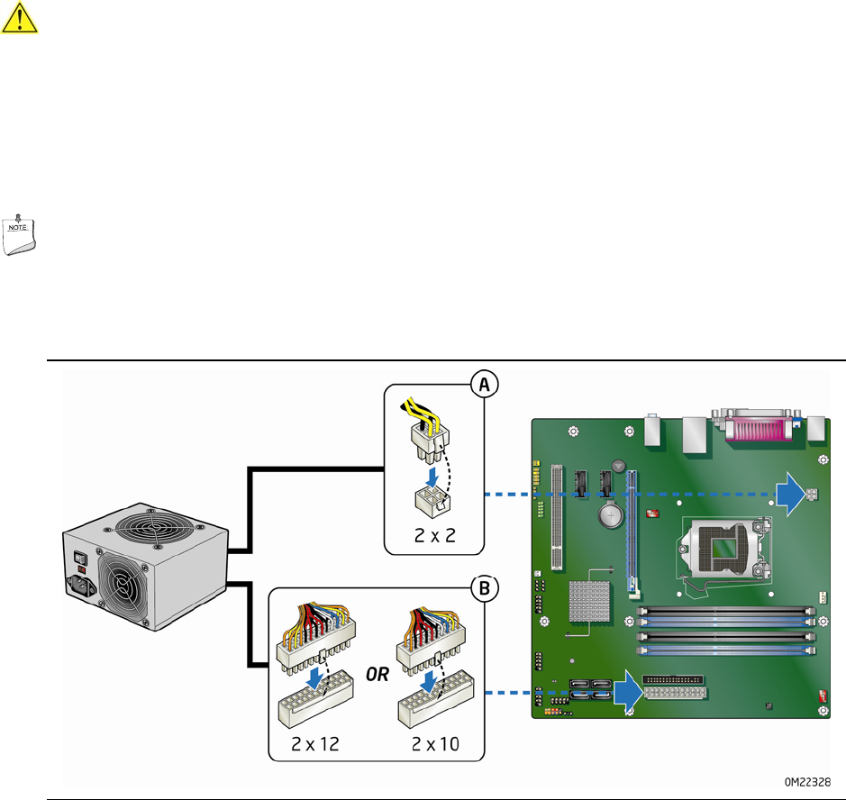
Figure 29 shows the location of the power connectors.
The 2 x 12 pin main powe
r
connector (Figure 29, B) is backwards compatible with ATX12V power supplies with
2 x 10 connectors.
NOTE
If your power supply has a 2 x 10 main power connector, it is recommended that you
do not install a PCI Express x16 graphics card unless it has a direct connection to the
power supply.
Figure 29. Connecting Power Supply Cables
1. Observe the precautions in "Before You Begin" on page 35.
2. Connect the 12 V processor core voltage power supply cable to the 2 x 2 pin
connector (Figure 29, A).
3. Con
n
ect the main power supply cable to the 2 x 12 pin connector (Figure 29, B).