
Intel Desktop Board DQ57TM Product Guide - English


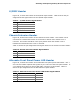


Table Of Contents
- Intel® Desktop Board DQ57TML Product Guide
- Revision History
- Preface
- Contents
- 1 Desktop Board Features
- 2 Installing and Replacing Desktop Board Components
- Before You Begin
- Installation Precautions
- Installing the I/O Shield
- Installing and Removing the Desktop Board
- Installing and Removing a Processor
- Installing and Removing System Memory
- Installing and Removing PCI Express x16 Graphics Cards
- Connecting the SATA Drive Cables
- Connecting a Diskette Drive
- Installing an Intel Z-U130 USB Solid-state Drive or Compatible Device
- Connecting to the Internal Headers
- Connecting to the Audio System
- Connecting Chassis Fan and Power Supply Cables
- Setting the BIOS Configuration Jumper
- Clearing Passwords in the BIOS Setup Program
- Replacing the Battery
- 3 Updating the BIOS
- A Error Messages and Indicators
- B Regulatory Compliance
Installing and Replacing Desktop Board Components
59
Figure 26, D shows the location of the front panel USB 2.0 header that supports an
Intel Z-U130 USB Solid-State Drive or compatible device and Table 14 shows the pin
assignments and
signal names.
Table 14. Front Panel USB Header with Intel Z-U130 USB Solid-State Drive or
Compatible Device Support Signal Names
Pin Signal Name Pin Signal Name
1
+5 VDC
2
+5 VDC
3
D-
4
D-
5
D+
6
D+
7
Ground
8
Ground
9
KEY (no pin)
10
LED#
NOTE
Computer systems that have an unshielded cable attached to a USB port might not
meet FCC Class B requirements, even if no device or a low-speed USB device is
attached to the cable. Use a shielded cable that meets the requirements for a
full-speed USB device.
Intel RPAT Header
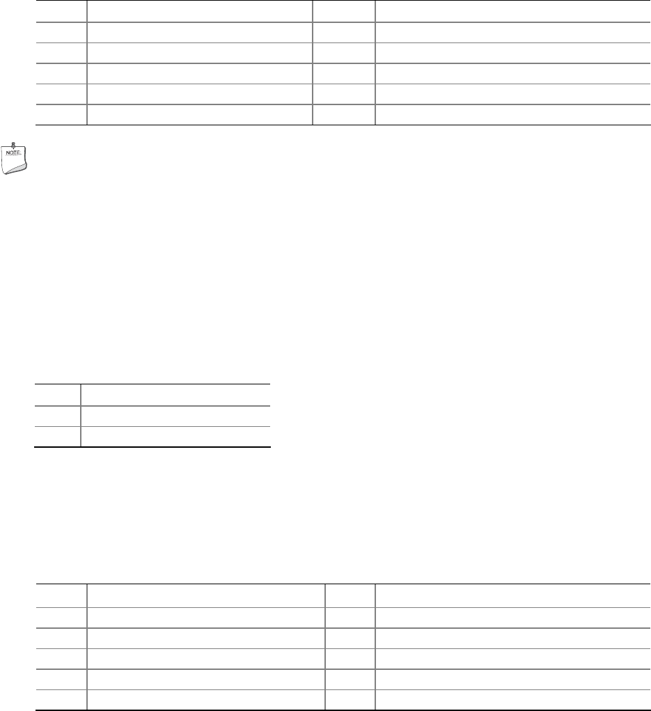
Figure 26, I shows the location of the Intel RPAT header. Table 15 shows the pin
assignments and signal names for the Intel RPAT header.
Table 15. Intel RPAT Header Signal Names
Pin Description
1 RPAT#
2 Ground
Serial Header
Figure 26, J shows the location of the serial header. Table 16 shows the pin
assignments and signal names for the serial header.
Table 16. Serial Port Header
Pin Signal Name Pin Signal Name
1 DCD (Data Carrier Detect) 2 RXD# (Receive Data)
3 TXD# (Transmit Data) 4 DTR (Data Terminal Ready)
5 Ground 6 DSR (Data Set Ready)
7 RTS (Request To Send) 8 CTS (Clear To Send)
9 RI (Ring Indicator) 10 Key (no pin)