
Intel Desktop Board DQ57TM Product Guide - English


Table Of Contents
- Intel® Desktop Board DQ57TML Product Guide
- Revision History
- Preface
- Contents
- 1 Desktop Board Features
- 2 Installing and Replacing Desktop Board Components
- Before You Begin
- Installation Precautions
- Installing the I/O Shield
- Installing and Removing the Desktop Board
- Installing and Removing a Processor
- Installing and Removing System Memory
- Installing and Removing PCI Express x16 Graphics Cards
- Connecting the SATA Drive Cables
- Connecting a Diskette Drive
- Installing an Intel Z-U130 USB Solid-state Drive or Compatible Device
- Connecting to the Internal Headers
- Connecting to the Audio System
- Connecting Chassis Fan and Power Supply Cables
- Setting the BIOS Configuration Jumper
- Clearing Passwords in the BIOS Setup Program
- Replacing the Battery
- 3 Updating the BIOS
- A Error Messages and Indicators
- B Regulatory Compliance
Intel Desktop Board DQ57TM Product Guide
54
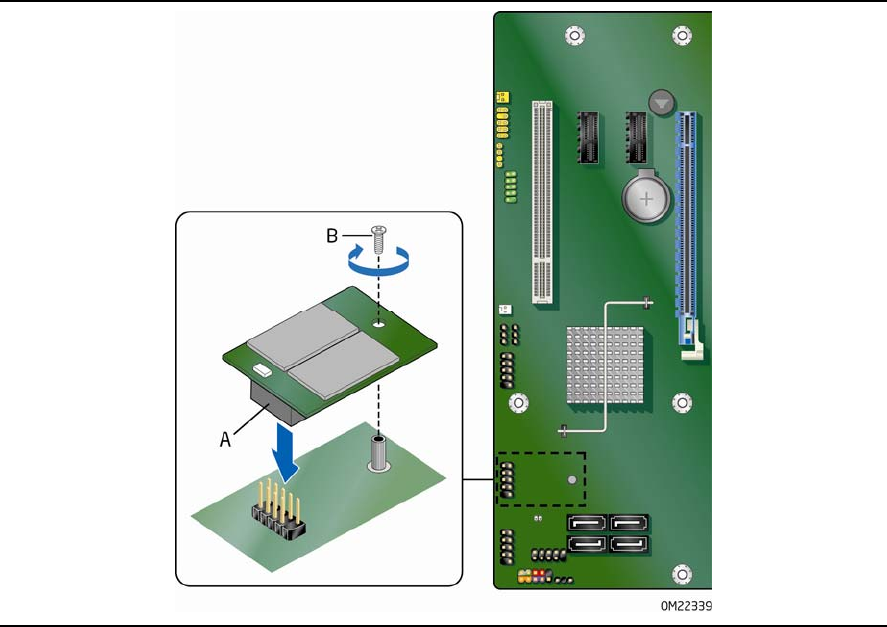
Installing an Intel Z-U130 USB Solid-state
Drive or Compatible Device
An Intel Z-U130 USB Solid-State Drive or compatible device can be installed on the
Desktop Board by using the onboard USB 2.0 header indicated in Figure 1, V. This
header provides support for the solid state
drive.
To install an Intel Z-U130 USB Solid-State Drive or compatible device on the Desktop
Board, follow these steps:
1. Observe the precautions in "Before You Begin" on page 35.
2. Al
i
gn the connector (Figure 25, A) on the bottom of the solid state drive with the
USB 2.
0 header on the Desktop Board. The connectors are keyed and will mate
correctly when the solid state drive is oriented as shown in Figure 25.
3. Secure the
sol
id state drive to the Desktop Board with the screw (Figure 25, B).
Figure 25. Installing an Intel Z-U130 USB Solid-State Drive
or Compatible Device