
Intel Desktop Board DQ57TM Product Guide - English
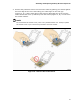

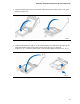


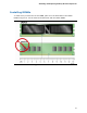


Table Of Contents
- Intel® Desktop Board DQ57TML Product Guide
- Revision History
- Preface
- Contents
- 1 Desktop Board Features
- 2 Installing and Replacing Desktop Board Components
- Before You Begin
- Installation Precautions
- Installing the I/O Shield
- Installing and Removing the Desktop Board
- Installing and Removing a Processor
- Installing and Removing System Memory
- Installing and Removing PCI Express x16 Graphics Cards
- Connecting the SATA Drive Cables
- Connecting a Diskette Drive
- Installing an Intel Z-U130 USB Solid-state Drive or Compatible Device
- Connecting to the Internal Headers
- Connecting to the Audio System
- Connecting Chassis Fan and Power Supply Cables
- Setting the BIOS Configuration Jumper
- Clearing Passwords in the BIOS Setup Program
- Replacing the Battery
- 3 Updating the BIOS
- A Error Messages and Indicators
- B Regulatory Compliance

Installing and Replacing Desktop Board Components
45
Installing and Removing System Memory
Desktop board DQ57TML has four 240-pin DDR3 DIMM sockets arranged as DIMM 0
and DIMM 1 in both Channel A and Channel B.
NOTE
A DIMM must be present in at least one of the DIMM 0 sockets when you are using
only one or two DIMMs with a processor that does not support Intel Graphics
Technology.
Guidelines for Dual-Channel Memory Configuration
Before installing DIMMs, read and follow these guidelines for dual-channel memory
configuration.
Two or Four DIMMs
Install a matched pair of DIMMs equal in speed and size (see Figure 16) in the DIMM 0
(blue) sockets of channels A and B.
Figure 16. Example Dual-Channel Memory Configuration with Two DIMMs