
Intel Desktop Board DQ57TM Product Guide - English
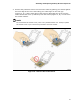

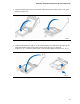


Table Of Contents
- Intel® Desktop Board DQ57TML Product Guide
- Revision History
- Preface
- Contents
- 1 Desktop Board Features
- 2 Installing and Replacing Desktop Board Components
- Before You Begin
- Installation Precautions
- Installing the I/O Shield
- Installing and Removing the Desktop Board
- Installing and Removing a Processor
- Installing and Removing System Memory
- Installing and Removing PCI Express x16 Graphics Cards
- Connecting the SATA Drive Cables
- Connecting a Diskette Drive
- Installing an Intel Z-U130 USB Solid-state Drive or Compatible Device
- Connecting to the Internal Headers
- Connecting to the Audio System
- Connecting Chassis Fan and Power Supply Cables
- Setting the BIOS Configuration Jumper
- Clearing Passwords in the BIOS Setup Program
- Replacing the Battery
- 3 Updating the BIOS
- A Error Messages and Indicators
- B Regulatory Compliance
Intel Desktop Board DQ57TM Product Guide
44
Installing a Processor Fan Heat Sink
Intel Desktop Board DQ57TML has mounting holes for a processor fan heat sink. For
instructions on how to attach the processor fan heat sink to the Desktop Board, refer
to the boxed processor manual or boxed thermal solution manual.
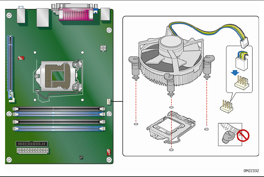
Connecting the Processor Fan Heat Sink Cable
Connect the processor fan heat sink power cable to the 4-pin processor fan header
(see Figure 13). A fan with a 4-pin connector as shown in Figure 13 is recommended.
Figure 15. Connecting the Processor Fan Heat Sink Power Cable to the
Processor Fan Header
Removing the Processor
For instructions on how to remove the processor fan heat sink and processor, refer to
the processor installation manual.