
Intel Desktop Board DQ57TM Product Guide - English


Table Of Contents
- Intel® Desktop Board DQ57TML Product Guide
- Revision History
- Preface
- Contents
- 1 Desktop Board Features
- 2 Installing and Replacing Desktop Board Components
- Before You Begin
- Installation Precautions
- Installing the I/O Shield
- Installing and Removing the Desktop Board
- Installing and Removing a Processor
- Installing and Removing System Memory
- Installing and Removing PCI Express x16 Graphics Cards
- Connecting the SATA Drive Cables
- Connecting a Diskette Drive
- Installing an Intel Z-U130 USB Solid-state Drive or Compatible Device
- Connecting to the Internal Headers
- Connecting to the Audio System
- Connecting Chassis Fan and Power Supply Cables
- Setting the BIOS Configuration Jumper
- Clearing Passwords in the BIOS Setup Program
- Replacing the Battery
- 3 Updating the BIOS
- A Error Messages and Indicators
- B Regulatory Compliance
Intel Desktop Board DQ57TM Product Guide
42
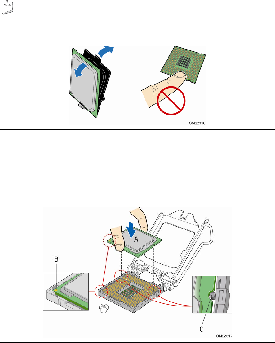
5. Remove the processor from its protective cover. Hold the processor only at the
edges, being careful not to touch the bottom of the processor (see Figure 11).
NOTE
Do not discard the processor cover. Always replace the processor cover if you
remove the processor from the socket.
Figure 11. Remove the Processor from the Protective Cover
6. Hold the processor with your thumb and index finger oriented as shown in
Figure 12 to align your fingers with the socket fi
nger cutouts. Make sure that the
processor Pin 1 indicator (gold triangle) is aligned with the Pin 1 chamfer on the
socket (Figure 12, B) and that the notches on the processo
r align with
the posts on
the socket (Figure 12, C). Lower the processor straigh
t down without tilting or
sliding it in the socket (Figure 12, A).
Figure 12. Install the Processor