
Intel Desktop Board DQ57TM Product Guide - English


Table Of Contents
- Intel® Desktop Board DQ57TML Product Guide
- Revision History
- Preface
- Contents
- 1 Desktop Board Features
- 2 Installing and Replacing Desktop Board Components
- Before You Begin
- Installation Precautions
- Installing the I/O Shield
- Installing and Removing the Desktop Board
- Installing and Removing a Processor
- Installing and Removing System Memory
- Installing and Removing PCI Express x16 Graphics Cards
- Connecting the SATA Drive Cables
- Connecting a Diskette Drive
- Installing an Intel Z-U130 USB Solid-state Drive or Compatible Device
- Connecting to the Internal Headers
- Connecting to the Audio System
- Connecting Chassis Fan and Power Supply Cables
- Setting the BIOS Configuration Jumper
- Clearing Passwords in the BIOS Setup Program
- Replacing the Battery
- 3 Updating the BIOS
- A Error Messages and Indicators
- B Regulatory Compliance
Intel Desktop Board DQ57TML Product Guide
32
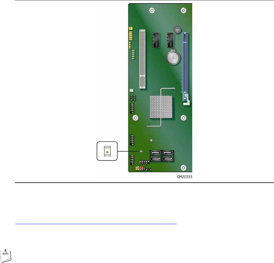
Figure 5. Location of the Standby Power Indicator
For more information on standby current requirements for the Desktop Board, refer to
the Technical Product Specification at
http://www.intel.com/support/motherboards/desktop/
.
Wake from USB
NOTE
Wake from USB requires the use of a USB peripheral that supports Wake from USB
and an operating system that supports Wake from USB.
USB bus activity wakes the computer from an ACPI S1 or S3 state.
PCI PME# Signal Wake-up Support
When the PME# signal on the PCI bus is asserted, the computer wakes from an
ACPI S1, S3, S4, or S5 state.
PCI Express WAKE# Signal Wake-up Support
When the WAKE# signal on a PCI Express bus add-in card is asserted, the computer
wakes from an ACPI S1, S3, S4, or S5 state.