
Intel Desktop Board DQ57TM Product Guide - English

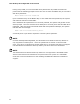


Table Of Contents
- Intel® Desktop Board DQ57TML Product Guide
- Revision History
- Preface
- Contents
- 1 Desktop Board Features
- 2 Installing and Replacing Desktop Board Components
- Before You Begin
- Installation Precautions
- Installing the I/O Shield
- Installing and Removing the Desktop Board
- Installing and Removing a Processor
- Installing and Removing System Memory
- Installing and Removing PCI Express x16 Graphics Cards
- Connecting the SATA Drive Cables
- Connecting a Diskette Drive
- Installing an Intel Z-U130 USB Solid-state Drive or Compatible Device
- Connecting to the Internal Headers
- Connecting to the Audio System
- Connecting Chassis Fan and Power Supply Cables
- Setting the BIOS Configuration Jumper
- Clearing Passwords in the BIOS Setup Program
- Replacing the Battery
- 3 Updating the BIOS
- A Error Messages and Indicators
- B Regulatory Compliance
Desktop Board Features
25
Intel ME “M” State LED
The board has a red-colored Intel ME “M” state LED (see Figure 3). The “M” state is
based on Intel ME status, as follows:
• M0 = Intel ME is in full control in S0.
• M3 = Intel ME is in full control in S3-S5 for “out of bound” Intel manageability.
• Moff = Intel ME is in sleep state after Intel ME timeout has occurred.
Figure 3. Location of the Intel ME “M” State LED
Table 5 shows the expected behavior of the Intel ME “M” state LED.
Table 5. Intel ME “M” State LED Behavior
Sx/M3 Sx/Moff S0/M0
LED blinks Off On