
Intel Desktop Board DQ57TM Product Guide - English


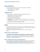
Table Of Contents
- Intel® Desktop Board DQ57TML Product Guide
- Revision History
- Preface
- Contents
- 1 Desktop Board Features
- 2 Installing and Replacing Desktop Board Components
- Before You Begin
- Installation Precautions
- Installing the I/O Shield
- Installing and Removing the Desktop Board
- Installing and Removing a Processor
- Installing and Removing System Memory
- Installing and Removing PCI Express x16 Graphics Cards
- Connecting the SATA Drive Cables
- Connecting a Diskette Drive
- Installing an Intel Z-U130 USB Solid-state Drive or Compatible Device
- Connecting to the Internal Headers
- Connecting to the Audio System
- Connecting Chassis Fan and Power Supply Cables
- Setting the BIOS Configuration Jumper
- Clearing Passwords in the BIOS Setup Program
- Replacing the Battery
- 3 Updating the BIOS
- A Error Messages and Indicators
- B Regulatory Compliance

Intel Desktop Board DQ57TML Product Guide
18
LAN Subsystem
The LAN subsystem includes:
• Intel 82578DM Gigabit (10/100/1000 Mb/s) Ethernet LAN controller with support
for:
⎯ Intel AMT 6.0
⎯ ASF 2.0
• RJ-45 LAN connector with integrated status LEDs
LAN software and drivers are available at http://downloadcenter.intel.com/
.
Two LEDs are built into the RJ-45 LAN connector located on the back panel (see
Figure 2). These LEDs indicate the status of the LAN as shown in Table 3.
Figure 2. LAN Status LEDs
Table 3. LAN Status LEDs States
LED LED Color LED State Indicates
A (Link/Activity) Off LAN link is not established
Green
On LAN link is established
Blinking LAN activity is occurring
N/A Off 10 Mb/s data rate
Green On 100 Mb/s data rate
B (Link Speed)
Yellow On 1000 Mb/s data rate