Intel® Desktop Board DQ57TML Product Guide Order Number: E95584-001
Revision History Revision -001 Revision History First release of the Intel® Desktop Board DQ57TML Product Guide Date June 2010 Disclaimer INFORMATION IN THIS DOCUMENT IS PROVIDED IN CONNECTION WITH INTEL® PRODUCTS. NO LICENSE, EXPRESS OR IMPLIED, BY ESTOPPEL OR OTHERWISE, TO ANY INTELLECTUAL PROPERTY RIGHTS IS GRANTED BY THIS DOCUMENT.
Preface This Product Guide gives information about board layout, component installation, BIOS update, and regulatory requirements for Intel® Desktop Board DQ57TML. Intended Audience The Product Guide is intended for technically qualified personnel. It is not intended for general audiences. Use Only for Intended Applications All Intel Desktop Boards are evaluated as Information Technology Equipment (I.T.E.
Intel Desktop Board DQ57TML Product Guide Terminology The table below gives descriptions of some common terms used in the product guide.
Contents 1 Desktop Board Features Supported Operating Systems..............................................................................11 Desktop Board Components.................................................................................12 Processor..........................................................................................................14 Intel® Q57 Express Chipset .................................................................................15 Main Memory......................
Intel Desktop Board DQ57TML Product Guide Installing a Processor ..................................................................................39 Installing a Processor Fan Heat Sink ..............................................................44 Connecting the Processor Fan Heat Sink Cable................................................44 Removing the Processor ..............................................................................44 Installing and Removing System Memory ......................
Contents B Regulatory Compliance Safety Standards ...............................................................................................79 Battery Caution ..........................................................................................79 European Union Declaration of Conformity Statement..............................................80 Product Ecology Statements ................................................................................81 Recycling Considerations ....................
Intel Desktop Board DQ57TML Product Guide 30. Location of the BIOS Configuration Jumper Block ..............................................63 31. Removing the Battery ...................................................................................69 32. Intel Desktop Board DQ57TML China RoHS Material Self Declaration Table............84 Tables 1. 2. 3. 4. 5. 6. 7. 8. 9. 10. 11. 12. 13. 14. 15. 16. 17. 18. 19. 20. 21. 22. 23. viii Feature Summary.......................................................
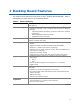
1 Desktop Board Features This chapter briefly describes the features of Intel® Desktop Board DQ57TML. Table 1 summarizes the major features of the Desktop Board. Table 1. Feature Summary Form Factor Processor Support MicroATX (243.84 millimeters [9.60 inches] x 243.84 millimeters [9.
Intel Desktop Board DQ57TML Product Guide Table 1. Feature Summary (continued) Peripheral Interfaces • Twelve USB 2.0 ports: ― Four ports are implemented with back panel connectors ― Eight ports are implemented with four dual-port internal headers (one header supports an Intel® Z-U130 USB Solid-state Drive or compatible device) • Four onboard Serial ATA (SATA) 3.
Desktop Board Features Supported Operating Systems The Desktop Board supports the following operating systems: • • • • • • • • • • • • • • • • • • • • Microsoft Microsoft Microsoft Microsoft Microsoft Microsoft Microsoft Microsoft Microsoft Microsoft Microsoft Microsoft Microsoft Microsoft Microsoft Microsoft Microsoft Microsoft Microsoft Microsoft Windows* 7 Ultimate 64-bit edition Windows 7 Ultimate 32-bit edition Windows 7 Professional 64-bit edition Windows 7 Professional 32-bit edition Windows 7 Hom
Intel Desktop Board DQ57TML Product Guide Desktop Board Components Figure 1 shows the approximate location of the major components on Intel Desktop Board DQ57TML. Figure 1.
Desktop Board Features Table 2. Intel Desktop Board DQ57TML Components Label Description A PCI bus add-in card connector B PCI Express 1.1 x1 add-in card connector C Battery D PCI Express 1.1 x1 add-in card connector E Speaker F PCI Express 2.
Intel Desktop Board DQ57TML Product Guide Online Support For more information on Intel Desktop Board DQ57TML consult the following online resources: • Intel Desktop Board DQ57TML http://www.intel.com/products/motherboard/index.ht m • Desktop Board Support http://www.intel.com/p/en_US/support?iid=hdr+supp ort • Available configurations for Intel Desktop Board DQ57TML http://ark.intel.com • Supported processors http://processormatch.intel.com • Chipset information http://www.intel.
Desktop Board Features Intel® Q57 Express Chipset The Intel Q57 Express Chipset, consisting of the Intel Q57 Platform Controller Hub (PCH), provides interfaces to the processor and the USB, SATA, LPC, audio, network, display, PCI, and PCI Express x1 interfaces. The PCH is a centralized controller for the board’s I/O paths.
Intel Desktop Board DQ57TML Product Guide Graphics Subsystem The board supports either integrated graphics (Intel Graphics Technology) or PCI Express 2.0 x16 graphics. Integrated Graphics The board supports integrated graphics through the Intel® Flexible Display Interface (Intel® FDI) for processors with Intel Graphics Technology. Digital Visual Interface Graphics Intel Desktop Board DQ57TML supports Digital Visual Interface (DVI) displays with a DVI-D port.
Desktop Board Features Audio Subsystem The board supports Intel High Definition Audio through a Realtek ALC662-VC audio codec. The Realtek ALC662-VC-based audio subsystem provides the following features: • • • • • 6-channel (5.1) audio with independent multi-streaming stereo Advanced jack sense for the back panel audio connectors that enables the audio codec to recognize the device that is connected to an audio port.
Intel Desktop Board DQ57TML Product Guide LAN Subsystem The LAN subsystem includes: • Intel 82578DM Gigabit (10/100/1000 Mb/s) Ethernet LAN controller with support for: ⎯ Intel AMT 6.0 • ⎯ ASF 2.0 RJ-45 LAN connector with integrated status LEDs LAN software and drivers are available at http://downloadcenter.intel.com/. Two LEDs are built into the RJ-45 LAN connector located on the back panel (see Figure 2). These LEDs indicate the status of the LAN as shown in Table 3. Figure 2.
Desktop Board Features USB 2.0 Support The board supports up to 12 USB 2.0 ports provided by two EHCI host controllers in the PCH that allow the use of EHCI-compatible drivers. The port arrangement is as follows: • • Four back panel connectors Eight front panel ports implemented as four dual-port internal headers. One of the internal headers supports an Intel Z-U130 USB Solid-state Drive or compatible device. USB 2.0 support requires both an operating system and drivers that fully support USB 2.
Intel Desktop Board DQ57TML Product Guide Expandability Intel Desktop Board DQ57TML provides the following expansion capability: • • • One PCI Express 2.0 x16 interface Two PCI Express 1.
Desktop Board Features BIOS Security Passwords The BIOS includes security features that restrict whether the BIOS Setup program can be accessed and who can boot the computer. A supervisor password and a user password can be set for the BIOS Setup and for booting the computer, with the following restrictions: • • • The supervisor password gives unrestricted access to view and change all Setup options.
Intel Desktop Board DQ57TML Product Guide During every POST, if a User hard disk drive password is set, POST execution will pause with the following prompt to force the user to enter the Master Key or User hard disk drive password: Enter Hard Disk Drive Password: Upon successful entry of the Master Key or User hard disk drive password, the system will continue with the normal POST. If the hard disk drive password is not correctly entered, the system will go back to the above prompt.
Desktop Board Features Platform Management and Protection Intel Desktop Board DQ57TML integrates several functions designed to manage the system and lower the total cost of ownership (TCO) of the system. These system management functions are designed to report errors, diagnose the system, and recover from system lockups without the aid of an external microcontroller. The board also includes several fan speed control and power management features.
Intel Desktop Board DQ57TML Product Guide The key features of Intel AMT include: • • • • • • • • • Secure Out of Band (OOB) system management that allows remote management of PCs regardless of system power or operating system state. Remote troubleshooting and recovery that can significantly reduce desk-side visits and potentially increasing efficiency of IT technical staff. Proactive alerting that decreases downtime and minimizes time to repair.
Desktop Board Features Intel ME “M” State LED The board has a red-colored Intel ME “M” state LED (see Figure 3). The “M” state is based on Intel ME status, as follows: • • • M0 = Intel ME is in full control in S0. M3 = Intel ME is in full control in S3-S5 for “out of bound” Intel manageability. Moff = Intel ME is in sleep state after Intel ME timeout has occurred. Figure 3. Location of the Intel ME “M” State LED Table 5 shows the expected behavior of the Intel ME “M” state LED. Table 5.
Intel Desktop Board DQ57TML Product Guide Intel® MEBX Reset Header This header (see Figure 4) allows you to reset the Intel AMT configuration to the factory defaults. Momentarily shorting pins 1 and 2 with a jumper (not supplied) will accomplish the following: • • • Return all Intel ME parameters to their default values. Delete any user entered information, including PID/PPS and user entered Hash Certificates.
Desktop Board Features Intel® Virtualization Technology (Intel® VT) Intel VT is a processor technology that enables a platform to run multiple operating systems and applications as independent machines, allowing one computer system to function as multiple "virtual" systems. It also provides the “assisted hardware virtualization” required by some operating systems for backward compatibility, such as Windows XP Mode for Microsoft Windows 7. NOTE Intel VT requires an Intel processor that supports Intel VT.
Intel Desktop Board DQ57TML Product Guide uses Client Initiated Remote Access (CIRA). This service is triggered in the same manner as Intel RPAT. Many of the features of Intel AMT are available with Intel RPAT and Fast Call for Help. These include Serial-over-LAN, IDE Redirection, KVM Redirection, and PC Alarm Clock. NOTE Intel RPAT requires an Intel vPro technology-enabled computer that has an Intel RPAT-enabled BIOS, a connection with a power source, and the Internet.
Desktop Board Features Fan Speed Control and Hardware Monitoring The features of the hardware monitoring and fan speed control include: • • • • • Intel Quiet System Technology, delivering acoustically-optimized thermal management Thermal sensors in the processor and the Intel PCH, as well as near the CPU voltage regulators and system memory Monitoring of system voltages to detect levels above or below acceptable values Thermally monitored closed-loop fan control for all three fans that can adjust fan spee
Intel Desktop Board DQ57TML Product Guide Hardware Support Power Connectors ATX12V-compliant power supplies can turn off the computer power through system control. When an ACPI-enabled computer receives the correct command, the power supply removes all non-standby voltages. When resuming from an AC power failure, the computer returns to the power state it was in before power was interrupted (either on or off).
Desktop Board Features Instantly Available PC Technology CAUTION For Instantly Available PC technology, the 5 V standby line for the power supply must be capable of delivering adequate +5 V standby current. Failure to provide adequate standby current when using this feature can damage the power supply and/or effect ACPI S3 sleep state functionality. Instantly Available PC technology enables the board to enter the ACPI S3 (Suspend-toRAM) sleep state.
Intel Desktop Board DQ57TML Product Guide Figure 5. Location of the Standby Power Indicator For more information on standby current requirements for the Desktop Board, refer to the Technical Product Specification at http://www.intel.com/support/motherboards/desktop/. Wake from USB NOTE Wake from USB requires the use of a USB peripheral that supports Wake from USB and an operating system that supports Wake from USB. USB bus activity wakes the computer from an ACPI S1 or S3 state.
Desktop Board Features Wake from Serial Devices Serial port activity wakes the computer from an ACPI S1 or S3 state. Wake from PS/2 Devices PS/2 device activity wakes the computer from an ACPI S1 or S3 state. Onboard Speaker A speaker is mounted on the Desktop Board. The speaker provides audible error code (beep code) information during the Power-On Self-Test (POST). Refer to Appendix A for a description of the beep codes that may be generated during the POST.
Intel Desktop Board DQ57TML Product Guide 34
2 Installing and Replacing Desktop Board Components This chapter tells you how to: • • • • • • • • • • • • • • Install the I/O shield Install and remove the Desktop Board Install and remove a processor Install and remove memory Install and remove a PCI Express x16 card Connect the SATA drive cables Connect a diskette drive Install an Intel Z-U130 USB Solid-state Drive or compatible device Connect to the internal headers Connect to the audio system Connect chassis fan and power supply cables Set the BIOS co
Intel Desktop Board DQ57TM Product Guide Installation Precautions When you install and test the Intel Desktop Board, observe all warnings and cautions in the installation instructions.
Installing and Replacing Desktop Board Components Installing the I/O Shield The Desktop Board comes with an I/O shield. When installed in the chassis, the shield blocks radio frequency transmissions, protects internal components from dust and foreign objects, and promotes correct airflow within the chassis. Install the I/O shield before installing the Desktop Board in the chassis. Place the shield inside the chassis as shown in Figure 6. Press the shield into place so that it fits tightly and securely.
Intel Desktop Board DQ57TM Product Guide Installing and Removing the Desktop Board CAUTION Only qualified technical personnel should perform this procedure. Disconnect the computer from its power source before performing the procedures described here. Failure to disconnect the power before you open the computer can result in personal injury or equipment damage. Refer to your chassis manual for instructions on installing and removing the Desktop Board.
Installing and Replacing Desktop Board Components Installing and Removing a Processor Instructions on how to install the processor on the Desktop Board are given below. Installing a Processor CAUTION Before installing or removing a processor, make sure the AC power has been removed by unplugging the power cord from the computer; the standby power LED should not be lit (see Figure 5 on page 32). Failure to do so could damage the processor and the board. To install a processor, follow these instructions: 1.
Intel Desktop Board DQ57TM Product Guide 3. Rotate the socket lever to lift the load plate away from the socket (Figure 9, A). Make sure that the load plate is in the fully open position (Figure 9, B) while being careful not to damage adjacent components. Figure 9.
Installing and Replacing Desktop Board Components 4. Remove the protective socket cover from the socket by placing your thumb against the front edge of the cover and resting your index finger on the rear grip (Figure 10, A). Lift the front edge of the socket to disengage the cover from the socket and lift the cover up and away from the socket (Figure 10, B). Do not touch the socket contacts. NOTE Do not discard the socket cover; save it for possible future use.
Intel Desktop Board DQ57TM Product Guide 5. Remove the processor from its protective cover. Hold the processor only at the edges, being careful not to touch the bottom of the processor (see Figure 11). NOTE Do not discard the processor cover. Always replace the processor cover if you remove the processor from the socket. Figure 11. Remove the Processor from the Protective Cover 6.
Installing and Replacing Desktop Board Components 7. Lower the load plate over the processor while leaving the socket lever in the open position (Figure 13). Figure 13. Lower the Load Plate 8. Lower the socket lever (Figure 14, B) while making sure that the front edge of the load plate slides under the shoulder screw cap as the lever is lowered (Figure 14, A). Latch the socket lever under the load plate tab (Figure 14, C, D). Figure 14.
Intel Desktop Board DQ57TM Product Guide Installing a Processor Fan Heat Sink Intel Desktop Board DQ57TML has mounting holes for a processor fan heat sink. For instructions on how to attach the processor fan heat sink to the Desktop Board, refer to the boxed processor manual or boxed thermal solution manual. Connecting the Processor Fan Heat Sink Cable Connect the processor fan heat sink power cable to the 4-pin processor fan header (see Figure 13).
Installing and Replacing Desktop Board Components Installing and Removing System Memory Desktop board DQ57TML has four 240-pin DDR3 DIMM sockets arranged as DIMM 0 and DIMM 1 in both Channel A and Channel B. NOTE A DIMM must be present in at least one of the DIMM 0 sockets when you are using only one or two DIMMs with a processor that does not support Intel Graphics Technology.
Intel Desktop Board DQ57TM Product Guide If additional memory is to be used, install another matched pair of DIMMs in the DIMM 1 (black) sockets of channels A and B (see Figure 17). Figure 17. Example Dual-Channel Memory Configuration with Four DIMMs Three DIMMs If you want to use three DIMMs in a dual-channel configuration, install a matched pair of DIMMs equal in speed and size in the DIMM 0 (blue) socket of channel A and the DIMM 0 (blue) socket of channel B.
Installing and Replacing Desktop Board Components Installing DIMMs To make sure you have the correct DIMM, place it on the illustration of the DDR3 DIMM in Figure 19. All the notches should match with the DDR3 DIMM. Figure 19.
Intel Desktop Board DQ57TM Product Guide To install a DIMM, follow these steps: 1. Observe the precautions in "Before You Begin" on page 35. 2. Turn off all peripheral devices connected to the computer. Turn off the computer and disconnect the AC power cord. 3. Remove the computer’s cover and locate the DIMM sockets (see Figure 20). 4. If a full length PCI Express graphics card is installed in the PCI Express x16 connector, remove the card to gain full access to the DIMM sockets. Figure 20.
Installing and Replacing Desktop Board Components Removing DIMMs To remove a DIMM, follow these steps: 1. 2. 3. 4. 5. 6. 7. 8. 9. Observe the precautions in "Before You Begin" on page 35. Turn off all peripheral devices connected to the computer. Turn off the computer. Remove the AC power cord from the computer. Remove the computer’s cover. If a full length PCI Express graphics card is installed in the PCI Express x16 connector, remove the card to gain access to the DIMMs.
Intel Desktop Board DQ57TM Product Guide Follow these instructions to install a PCI Express x16 graphics card: 1. Observe the precautions in "Before You Begin" on page 35. 2. Place the card in the PCI Express x16 connector (Figure 21, A) and press down on the card until it is completely seated in the connector and the card retention notch on the card snaps into place around the retention mechanism pin on the connector. 3.
Installing and Replacing Desktop Board Components Removing a PCI Express x16 Graphics Card Follow these instructions to remove a PCI Express x16 graphics card from a connector: 1. Observe the precautions in "Before You Begin" on page 35. 2. Disconnect the monitor cable from the graphics card back panel connector. 3. Remove the screw (Figure 22, A) that secures the card’s metal bracket to the chassis back panel. 4.
Intel Desktop Board DQ57TM Product Guide Connecting the SATA Drive Cables SATA cables support the Serial ATA protocol. Each cable can be used to connect one internal SATA drive to the Desktop Board. For correct cable function: 1. Observe the precautions in “Before You Begin” on page 35. 2. Attach one end of the SATA cable to one of the SATA connectors on the board (Figure 23, A) and attach the other end of the cable to the SATA drive (Figure 23, B). Figure 23.
Installing and Replacing Desktop Board Components Connecting a Diskette Drive A diskette drive cable can be used to connect a single diskette drive to the Desktop Board. For correct function of the diskette drive: 1. Observe the precautions in "Before You Begin" on page 35. 2. Attach the cable end labeled P1 to the diskette drive connector on the Intel Desktop Board (Figure 24, A). 3. Attach the cable end labeled P2 to the connector on the diskette drive (Figure 24, B). Figure 24.
Intel Desktop Board DQ57TM Product Guide Installing an Intel Z-U130 USB Solid-state Drive or Compatible Device An Intel Z-U130 USB Solid-State Drive or compatible device can be installed on the Desktop Board by using the onboard USB 2.0 header indicated in Figure 1, V. This header provides support for the solid state drive. To install an Intel Z-U130 USB Solid-State Drive or compatible device on the Desktop Board, follow these steps: 1. Observe the precautions in "Before You Begin" on page 35. 2.
Installing and Replacing Desktop Board Components Connecting to the Internal Headers Before connecting cables to any of the internal headers, observe the precautions in “Before You Begin” on page 35. Figure 26 shows the location of the internal headers and connectors on Intel Desktop Board DQ57TML. Figure 26.
Intel Desktop Board DQ57TM Product Guide Front Panel Audio Header The front panel audio header shown in Figure 26, A supports both Intel High Definition Audio and AC ’97 Audio. Table 6 shows the pin assignments and signal names for HD Audio and Table 7 shows the pin assignments and signal names for AC ’97 Audio. Table 6.
Installing and Replacing Desktop Board Components S/PDIF Header Figure 26, C shows the location of the S/PDIF output header. Table 9 shows the pin assignments and signal names for the S/PDIF output header. Table 9. S/PDIF Header Signal Names Pin Description 1 Ground 2 S/PDIF Out 3 Key (no pin) 4 +5 VDC Chassis Intrusion Header Figure 26, E shows the location of the chassis intrusion header.
Intel Desktop Board DQ57TM Product Guide Front Panel Header Figure 26, G shows the location of the front panel header. Table 12 shows the pin assignments and signal names for the front panel header. Table 12.
Installing and Replacing Desktop Board Components Figure 26, D shows the location of the front panel USB 2.0 header that supports an Intel Z-U130 USB Solid-State Drive or compatible device and Table 14 shows the pin assignments and signal names. Table 14.
Intel Desktop Board DQ57TM Product Guide Connecting to the Audio System After installing the Realtek audio driver from the Intel® Express Installer DVD-ROM, the multi-channel audio feature can be enabled. Figure 27 shows the back panel audio connectors. The default connector assignments are shown in the table. Item Description A Line in B Line out (front speaker/headphones) C Mic in Figure 27.
Installing and Replacing Desktop Board Components Connecting Chassis Fan and Power Supply Cables Connecting Chassis Fan Cables Connect chassis fan cables to the chassis fan headers on the Desktop Board. Figure 28 shows the location of the chassis fan headers. Figure 28.
Intel Desktop Board DQ57TM Product Guide Connecting Power Supply Cables CAUTION Failure to use an appropriate power supply and/or not connecting the 12 V power connector (Figure 29, A) to the Desktop Board may result in damage to the board or the system may not function properly. Figure 29 shows the location of the power connectors. The 2 x 12 pin main power connector (Figure 29, B) is backwards compatible with ATX12V power supplies with 2 x 10 connectors.
Installing and Replacing Desktop Board Components Setting the BIOS Configuration Jumper NOTE Always turn off the power and unplug the power cord from the computer before moving the jumper. Moving the jumper with the power on may result in unreliable computer operation. Figure 30 shows the location of the Desktop Board’s BIOS configuration jumper block. Figure 30.
Intel Desktop Board DQ57TM Product Guide The three-pin BIOS jumper block enables board configuration to be done in the BIOS Setup program. Table 17 shows the jumper settings for the BIOS Setup program modes. Table 17. Jumper Settings for the BIOS Setup Program Modes Jumper Setting Mode Description Normal (default) (1-2) The BIOS uses the current configuration and passwords for booting. Configure (2-3) After the Power-On Self-Test (POST) runs, the BIOS displays the Maintenance Menu.
Installing and Replacing Desktop Board Components 10. Turn off the computer. Disconnect the computer’s power cord from the AC power source. 11. Remove the computer cover. 12. To restore normal operation, place the jumper on pins 1-2 as shown below. 13. Replace the cover, plug in the computer, and turn on the computer. Replacing the Battery A coin-cell battery (CR2032) powers the real-time clock and CMOS memory.
Intel Desktop Board DQ57TM Product Guide VIKTIGT! Risk för explosion om batteriet ersätts med felaktig batterityp. Batterier ska kasseras enligt de lokala miljövårdsbestämmelserna. VARO Räjähdysvaara, jos pariston tyyppi on väärä. Paristot on kierrätettävä, jos se on mahdollista. Käytetyt paristot on hävitettävä paikallisten ympäristömääräysten mukaisesti. VORSICHT Bei falschem Einsetzen einer neuen Batterie besteht Explosionsgefahr.
Installing and Replacing Desktop Board Components Προσοχή Υπάρχει κίνδυνος για έκρηξη σε περίπτωση που η μπαταρία αντικατασταθεί από μία λανθασμένου τύπου. Οι μπαταρίες θα πρέπει να ανακυκλώνονται όταν κάτι τέτοιο είναι δυνατό. Η απόρριψη των χρησιμοποιημένων μπαταριών πρέπει να γίνεται σύμφωνα με τους κατά τόπο περιβαλλοντικούς κανονισμούς. VIGYÁZAT Ha a telepet nem a megfelelő típusú telepre cseréli, az felrobbanhat. A telepeket lehetőség szerint újra kell hasznosítani.
Intel Desktop Board DQ57TM Product Guide POZOR Zamenjava baterije z baterijo drugačnega tipa lahko povzroči eksplozijo. Če je mogoče, baterije reciklirajte. Rabljene baterije zavrzite v skladu z lokalnimi okoljevarstvenimi predpisi. . UYARI Yanlış türde pil takıldığında patlama riski vardır. Piller mümkün olduğunda geri dönüştürülmelidir. Kullanılmış piller, yerel çevre yasalarına uygun olarak atılmalıdır. OСТОРОГА Використовуйте батареї правильного типу, інакше існуватиме ризик вибуху.
Installing and Replacing Desktop Board Components To replace the battery, follow these steps: 1. Observe the precautions in "Before You Begin" (see page 35). 2. Turn off all peripheral devices connected to the computer. Disconnect the computer’s power cord from the AC power source (wall outlet or power adapter). 3. Remove the computer cover. 4. Locate the battery on the board (see Figure 31). 5. With a medium flat-bladed screwdriver, gently pry the battery free from its connector.
Intel Desktop Board DQ57TM Product Guide 70
3 Updating the BIOS The BIOS Setup program can be used to view and change the BIOS settings for the computer. You can access the BIOS Setup program by pressing the key after the Power-On Self-Test (POST) memory test begins and before the operating system boot begins. This chapter tells you how to update the BIOS by either using the Intel® Express BIOS Update utility or the Iflash Memory Update utility, and how to recover the BIOS if an update fails.
Intel Desktop Board DQ57TML Product Guide Updating the BIOS with the ISO Image BIOS Update File or the Iflash Memory Update Utility You can use the information in this section to update the BIOS using either the Iflash Memory Update Utility or the ISO Image BIOS update file. Obtaining the BIOS Update File You can update to a new version of the BIOS by using the ISO Image BIOS update file (recommended), or Iflash BIOS update file.
Updating the BIOS Updating the BIOS with the ISO Image BIOS Update File The ISO Image BIOS update allows for the update of an Intel® Desktop Board BIOS to the latest production release regardless of the operating system installed on the computer's hard disk drive and without the need to remove the BIOS configuration jumper. It requires a blank CD-R, a read/writeable CD drive, and software capable of uncompressing and writing the ISO image file to CD.
Intel Desktop Board DQ57TML Product Guide Updating the BIOS with the Iflash Memory Update Utility With the Iflash Memory update utility you can update the system BIOS from a bootable CD-ROM, bootable USB flash drive, or other bootable USB media. The utility available on the Intel World Wide Web site provides a simple method for creating a bootable CD-ROM that will automatically update your BIOS.
Updating the BIOS Additionally, the F7 prompt display can be enabled during start-up by following these steps: 1. 2. 3. 4. 5. Power the computer on. Enter the BIOS Setup by pressing F2 during boot. Go to the Advanced > Boot Configuration menu. Enable Display F7 to Update BIOS. Press F10 to save and exit. Recovering the BIOS It is unlikely that anything will interrupt the BIOS update; however, if an interruption occurs, the BIOS could be damaged.
Intel Desktop Board DQ57TML Product Guide 76
A Error Messages and Indicators Intel Desktop Board DQ57TML reports POST errors in two ways: • • By sounding a beep code and blinking the front panel power LED By displaying an error message on the monitor BIOS Error Codes Whenever a recoverable error occurs during POST, the BIOS causes the board’s speaker to beep and the front panel power LED to blink an error message indicating the problem (see Table 18). Table 18. BIOS Beep Codes Type Pattern Frequency/Comments F2 Setup/F10 Boot Menu Prompt One 0.
Intel Desktop Board DQ57TML Product Guide Table 19. Front-panel Power LED Blink Codes Type Pattern F2 Setup/F10 Boot Menu Prompt None Note BIOS update in progress Off when the update begins, then on for 0.5 seconds, then off for 0.5 seconds. The pattern repeats until the BIOS update is complete. Video error (no addin graphics card installed) On-off (1.0 second each) two times, then a 2.5-second pause (off), the entire pattern repeats (blink and pause) until the system is powered off.
B Regulatory Compliance This appendix contains the following regulatory compliance information for Intel Desktop Board DQ57TML: • • • • • Safety standards European Union Declaration of Conformity statement Product Ecology statements Electromagnetic Compatibility (EMC) regulations Product certifications Safety Standards Intel Desktop Board DQ57TML complies with the safety standards stated in Table 21 when correctly installed in a compatible host system. Table 21.
Intel Desktop Board DQ57TML Product Guide European Union Declaration of Conformity Statement We, Intel Corporation, declare under our sole responsibility that the product Intel® Desktop Board DQ57TML is in conformity with all applicable essential requirements necessary for CE marking, following the provisions of the European Council Directives 2004/108/EC (EMC Directive), 2006/95/EC (Low Voltage Directive), and 2002/95/EC (ROHS Directive).
Regulatory Compliance Polski Niniejszy produkt jest zgodny z postanowieniami Dyrektyw Unii Europejskiej 2004/108/EC, 206/95/EC i 2002/95/EC. Portuguese Este produto cumpre com as normas da Diretiva Européia 2004/108/EC, 2006/95/EC & 2002/95/EC. Español Este producto cumple con las normas del Directivo Europeo 2004/108/EC, 2006/95/EC & 2002/95/EC. Slovensky Tento produkt je v súlade s ustanoveniami európskych direktív 2004/108/EC, 2006/95/EC a 2002/95/EC.
Intel Desktop Board DQ57TML Product Guide Deutsch Als Teil von Intels Engagement für den Umweltschutz hat das Unternehmen das Intel Produkt-Recyclingprogramm implementiert, das Einzelhandelskunden von Intel Markenprodukten ermöglicht, gebrauchte Produkte an ausgewählte Standorte für ordnungsgemäßes Recycling zurückzugeben. Details zu diesem Programm, einschließlich der darin eingeschlossenen Produkte, verfügbaren Standorte, Versandanweisungen, Bedingungen usw., finden Sie auf der http://intel.
Regulatory Compliance Portuguese Como parte deste compromisso com o respeito ao ambiente, a Intel implementou o Programa de Reciclagem de Produtos para que os consumidores finais possam enviar produtos Intel usados para locais selecionados, onde esses produtos são reciclados de maneira adequada. Consulte o site http://intel.
Intel Desktop Board DQ57TML Product Guide China RoHS Intel Desktop Board DQ57TML is a China RoHS-compliant product. The China Ministry of Information Industry (MII) stipulates that a material Self Declaration Table (SDT) must be included in a product’s user documentation. The SDT for Intel Desktop Board DQ57TML is shown in Figure 32. Figure 32.
Regulatory Compliance EMC Regulations Intel Desktop Board DQ57TML complies with the EMC regulations stated in Table 22 when correctly installed in a compatible host system. Table 22. EMC Regulations Regulation Title FCC 47 CFR Part 15, Subpart B Title 47 of the Code of Federal Regulations, Part 15, Subpart B, Radio Frequency Devices. (USA) ICES-003 Interference-Causing Equipment Standard, Digital Apparatus.
Intel Desktop Board DQ57TML Product Guide radio or television reception, which can be determined by turning the equipment off and on, the user is encouraged to try to correct the interference by one or more of the following measures: • • • • Reorient or relocate the receiving antenna. Increase the separation between the equipment and the receiver. Connect the equipment to an outlet on a circuit other than the one to which the receiver is connected.
Regulatory Compliance Korea Class B Statement Korea Class B Statement translation: This equipment is for home use, and has acquired electromagnetic conformity registration, so it can be used not only in residential areas, but also other areas. Ensure Electromagnetic Compatibility (EMC) Compliance Before computer integration, make sure that the power supply and other modules or peripherals, as applicable, have passed Class B EMC testing and are marked accordingly.
Intel Desktop Board DQ57TML Product Guide Product Certifications Board-Level Certifications Intel Desktop Board DQ57TML has the regulatory compliance marks shown in Table 23. Table 23. Regulatory Compliance Marks Description UL joint US/Canada Recognized Component mark. Includes adjacent UL file number for Intel Desktop Boards: E210882. Mark FCC Declaration of Conformity logo mark for Class B equipment. CE mark.
Regulatory Compliance Chassis- and Component-Level Certifications Ensure that the chassis and certain components; such as the power supply, peripheral drives, wiring, and cables; are components certified for the country or market where used. Agency certification marks on the product are proof of certification. Typical product certifications include: In Europe The CE mark indicates compliance with all applicable European requirements.
Intel Desktop Board DQ57TML Product Guide In Canada A nationally recognized certification mark such as CSA or cUL signifies compliance with safety requirements. The Industry Canada statement at the front of this product guide demonstrates compliance with Canadian EMC regulations. ENERGY STAR*, e-Standby, and ErP Compliance The US Department of Energy and the US Environmental Protection Agency have continually revised the ENERGY STAR requirements.