Intel® Desktop Board DP965LT Product Guide Order Number: D46810-003
Revision History Revision -001 -002 -003 Revision History First release of the Intel® Desktop Board DP965LT Product Guide Second release of the Intel® Desktop Board DP965LT Product Guide Added operating system support Date June 2006 September 2006 December 2006 If an FCC declaration of conformity marking is present on the board, the following statement applies: FCC Declaration of Conformity This device complies with Part 15 of the FCC Rules.
Preface This Product Guide gives information about board layout, component installation, BIOS update, and regulatory requirements for Intel® Desktop Board DP965LT. Intended Audience The Product Guide is intended for technically qualified personnel. It is not intended for general audiences. Use Only for Intended Applications All Intel desktop boards are evaluated as Information Technology Equipment (I.T.E.
Intel Desktop Board DP965LT Product Guide Terminology The table below gives descriptions of some common terms used in the product guide.
Contents 1 Desktop Board Features Supported Operating Systems .............................................................................. 10 Desktop Board Components.................................................................................. 11 Processor ........................................................................................................... 13 Main Memory ......................................................................................................
Intel Desktop Board DP965LT Product Guide Installing and Removing a Processor...................................................................... 29 Installing a Processor ................................................................................... 29 Installing the Processor Fan Heat Sink............................................................ 32 Connecting the Processor Fan Heat Sink Cable ................................................ 32 Removing the Processor ............................
Contents B Regulatory Compliance Safety Regulations .............................................................................................. 65 Place Battery Marking .................................................................................. 65 European Union Declaration of Conformity Statement .............................................. 66 Product Ecology Statements ................................................................................. 67 Lead-Free Desktop Board ................
Intel Desktop Board DP965LT Product Guide Tables 1. 2. 3. 4. 5. 6. 7. 8. 9. 10. 11. 12. 13. 14. 15. 16. 17. 18. viii Feature Summary ............................................................................................9 Desktop Board DP965LT Components............................................................... 12 LAN Connector LEDs ...................................................................................... 17 HD Audio Link Header Signal Names ........................................
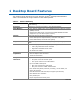
1 Desktop Board Features This chapter briefly describes the main features of Intel® Desktop Board DP965LT. Table 1 summarizes the major features of the desktop board. Table 1. Feature Summary Form Factor ATX (320.04 millimeters [11.60 inches] x 243.84 millimeters [9.60 inches]) Processor Support for an Intel® processor in the LGA775 package Main Memory • Four 240-pin, DDR2 1.
Intel Desktop Board DP965LT Product Guide Table 1.
Desktop Board Features Desktop Board Components Figure 1 shows the approximate location of the major components on Desktop Board DP965LT. Figure 1.
Intel Desktop Board DP965LT Product Guide Table 2.
Desktop Board Features Processor CAUTION Failure to use the appropriate power supply and/or not connecting the 12 V (2 x 2 pin) power connector to the desktop board may result in damage to the board, or the system may not function properly. Desktop Board DP965LT supports an Intel processor in the LGA775 package. Processors are not included with the desktop board and must be purchased separately. The processor connects to the desktop board through the LGA775 socket.
Intel Desktop Board DP965LT Product Guide Main Memory NOTE To be fully compliant with all applicable Intel ® SDRAM memory specifications, the board should be populated with DIMMs that support the Serial Presence Detect (SPD) data structure. If your memory modules do not support SPD, you will see a notification to this effect on the screen at power up. The BIOS will attempt to configure the memory controller for normal operation.
Desktop Board Features Intel® P965 Express Chipset The Intel P965 Express Chipset consists of the following devices: • • Intel P965 Express Chipset Memory Controller Hub (MCH) Intel 82801HB I/O Controller Hub (ICH8) Related Links: Go to the following link for more information about the Intel P965 Express Chipset: http://developer.intel.com/design/nav/pcserver.htm Onboard Audio Subsystem Desktop Board DP965LT has a flexible 6-channel (5.
Intel Desktop Board DP965LT Product Guide Input/Output (I/O) Controller The super I/O controller features the following: • • • • • • • • Low pin count (LPC) interface One serial port header One parallel port with Extended Capabilities Port (ECP) and Enhanced Parallel Port (EPP) support Serial IRQ interface compatible with serialized IRQ support for PCI systems PS/2-style mouse and keyboard interfaces Interface for one 1.2 MB or 1.
Desktop Board Features Table 3 describes the LED states when the board is powered up and the LAN subsystem is operating. Table 3. LAN Connector LEDs LED LED Color LED State Indicates A Green Off LAN link is not established On LAN link is established B Blinking LAN activity is occurring N/A Off 10 Mb/s data rate Green On 100 Mb/s data rate Yellow On 1000 Mb/s data rate Hi-Speed USB 2.
Intel Desktop Board DP965LT Product Guide Serial ATA The desktop board supports four Serial ATA channels (3.0 Gb/s) via ICH8, connecting one device per channel. Expandability For system expansion, the desktop board provides the following: • • • Three PCI Express x1 connectors One PCI Express x 16 connector Three PCI bus connectors BIOS The BIOS provides the Power-On Self-Test (POST), the BIOS Setup program, the PCI/PCI Express and IDE auto-configuration utilities, and the video BIOS.
Desktop Board Features Security Passwords The BIOS includes security features that restrict whether the BIOS Setup program can be accessed and who can boot the computer. A supervisor password and a user password can be set for the BIOS Setup and for booting the computer, with the following restrictions: • • • The supervisor password gives unrestricted access to view and change all Setup options.
Intel Desktop Board DP965LT Product Guide Chassis Intrusion The board supports a chassis security feature that detects if the chassis cover has been removed. The security feature uses a mechanical switch on the chassis that can be connected to the chassis intrusion header on the desktop board. See Figure 26 on page 50 for the location of the chassis intrusion header.
Desktop Board Features Fan Headers The function/operation of the fans is as follows: • • • • • The fans are on when the computer is in the ACPI S0 state. The fans are off when the computer is in the ACPI S3, S4, or S5 state. Each fan header is wired to a tachometer input of the hardware monitoring and control device. All fan headers support closed-loop fan control that can adjust the fan speed or switch the fan on or off as needed. All fan headers have a +12 V dc connection.
Intel Desktop Board DP965LT Product Guide The desktop board supports the PCI Bus Power Management Interface Specification. Add-in cards that support this specification can participate in power management and can be used to wake the computer. +5 V Standby Power Indicator LED CAUTION If the AC power has been switched off and the standby power indicator is still lit, disconnect the power cord before installing or removing any devices connected to the board.
Desktop Board Features Wake from USB NOTE Wake from USB requires the use of a USB peripheral that supports Wake from USB. USB bus activity wakes the computer from an ACPI S3 state. Wake from PS/2 Keyboard/Mouse PS/2 keyboard/mouse activity wakes the computer from an ACPI S3 state. PME# Signal Wake-up Support When the PME# signal on the PCI bus is asserted, the computer wakes from an ACPI S3, S4, or S5 state.
Intel Desktop Board DP965LT Product Guide 24
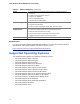
2 Installing and Replacing Desktop Board Components This chapter tells you how to: • • • • • • • • • • • • Install the I/O shield Install and remove the desktop board Install and remove a processor Install and remove memory Install and remove a PCI Express x16 card Connect the IDE and Serial ATA cables Connect to the internal headers Connect to the flexible audio system Connect the chassis fan and power cables Set the BIOS configuration jumper Clear passwords Replace the battery Before You Begin CAUTIONS
Intel Desktop Board DP965LT Product Guide Installation Precautions When you install and test the Intel desktop board, observe all warnings and cautions in the installation instructions.
Installing and Replacing Desktop Board Components Installing the I/O Shield The desktop board comes with an I/O shield. When installed in the chassis, the shield blocks radio frequency transmissions, protects internal components from dust and foreign objects, and promotes correct airflow within the chassis. Install the I/O shield before installing the desktop board in the chassis. Place the shield inside the chassis as shown in Figure 4. Press the shield into place so that it fits tightly and securely.
Intel Desktop Board DP965LT Product Guide Installing and Removing the Desktop Board CAUTION Only qualified technical personnel should do this procedure. Disconnect the computer from its power source before performing the procedures described here. Failure to disconnect the power before you open the computer can result in personal injury or equipment damage. Refer to your chassis manual for instructions on installing and removing the desktop board.
Installing and Replacing Desktop Board Components Installing and Removing a Processor Instructions on how to install the processor to the desktop board are given below. Installing a Processor CAUTION Before installing or removing the processor, make sure the AC power has been removed by unplugging the power cord from the computer; the standby power LED should not be lit (see Figure 3 on page 22). Failure to do so could damage the processor and the board.
Intel Desktop Board DP965LT Product Guide 4. Remove the plastic protective socket cover from the load plate (Figure 8). Do not discard the protective socket cover. Always replace the socket cover if the processor is removed from the socket. Figure 8. Remove the Protective Socket Cover 5. Remove the processor from the protective processor cover. Hold the processor only at the edges, being careful not to touch the bottom of the processor (see Figure 9). Do not discard the protective processor cover.
Installing and Replacing Desktop Board Components 6. Hold the processor with your thumb and index fingers oriented as shown in Figure 10. Make sure fingers align to the socket cutouts (Figure 10, A). Align notches (Figure 10, B) with the socket (Figure 10, C). Lower the processor straight down without tilting or sliding the processor in the socket. Figure 10. Install Processor 7. Pressing down on the load plate (Figure 11, A) close and engage the socket lever (Figure 11, B). Figure 11.
Intel Desktop Board DP965LT Product Guide Installing the Processor Fan Heat Sink Desktop Board DP965LT has an integrated processor fan heat sink retention mechanism (RM).
Installing and Replacing Desktop Board Components Removing the Processor For instructions on how to remove the processor fan heat sink and processor, refer to the processor installation manual or the Intel World Wide Web site at: Integration of the Boxed Intel® Pentium® 4 Processor in the 775-Land Package 1 Installing and Removing Memory NOTE To be fully compliant with all applicable Intel SDRAM memory specifications, the board requires DIMMs that support the Serial Presence Detect (SPD) data structure.
Intel Desktop Board DP965LT Product Guide If additional memory is to be used, install another matched pair of DIMMs in DIMM 1 (black) in both channels A and B (see Figure 14). Figure 14. Dual Channel Memory Configuration Example 2 Three DIMMs Install a matched pair of DIMMs equal in speed and size in DIMM 0 (blue) and DIMM 1 (black) of channel A. Install a DIMM equal in speed and total size of the DIMMs installed in channel A in either DIMM 0 or DIMM 1 of channel B (see Figure 15). Figure 15.
Installing and Replacing Desktop Board Components Installing DIMMs To make sure you have the correct DIMM, place it on the illustration of the DDR2 DIMM in Figure 16. All the notches should match with the DDR2 DIMM. Figure 16.
Intel Desktop Board DP965LT Product Guide NOTE Memory must be installed in the Channel A, DIMM 0 socket to enable Intel Quiet System Technology. To install a DIMM, follow these steps: 1. Observe the precautions in "Before You Begin" on page 25. 2. Turn off all peripheral devices connected to the computer. Turn off the computer and disconnect the AC power cord. 3. Remove the computer’s cover and locate the DIMM sockets (see Figure 17). Figure 17. Installing a DIMM 4.
Installing and Replacing Desktop Board Components Removing DIMMs To remove a DIMM, follow these steps: Observe the precautions in "Before You Begin" on page 25. Turn off all peripheral devices connected to the computer. Turn off the computer. Remove the AC power cord from the computer. Remove the computer’s cover. Gently spread the retaining clips at each end of the DIMM socket. The DIMM pops out of the socket. 6.
Intel Desktop Board DP965LT Product Guide Installing and Removing a PCI Express x16 Card CAUTION When installing a PCI Express x16 card on the desktop board, ensure that the card is fully seated in the PCI Express x16 connector before you power on the system. If the card is not fully seated in the PCI Express connector, an electrical short may result across the PCI Express connector pins.
Installing and Replacing Desktop Board Components Removing the PCI Express x16 Card Follow these instructions to remove the PCI Express x16 card from the connector: 1. Observe the precautions in "Before You Begin" on page 25. 2. Remove the screw (Figure 19, A) that secures the card’s metal bracket to the chassis back panel. 3. Push back on the card ejector lever (Figure 19, B) to release the card from the connector (C). 4. Pull the card straight up. Figure 19.
Intel Desktop Board DP965LT Product Guide Connecting the IDE Cable The IDE cable can connect two drives to the desktop board. The cable supports the ATA-66/100 transfer protocol. Figure 20 shows the correct installation of the cable. NOTES ATA-66/100 compatible cables are backward compatible with drives using slower IDE transfer protocols.
Installing and Replacing Desktop Board Components Connecting the Serial ATA (SATA) Cable The SATA cable supports the Serial ATA protocol and connects a single drive to the desktop board. For correct cable function: 1. Observe the precaution in "Before You Begin" on page 25. 2. Attach the locking cable end to the connector on the board (Figure 21, A). 3. Attach the cable end without the lock to the drive (Figure 21, B). Figure 21.
Intel Desktop Board DP965LT Product Guide Connecting to Internal Headers Before connecting cables to the internal headers, observe the precautions in "Before You Begin" on page 25. Figure 22 shows the location of the internal headers. Item Description A HD Audio Link B IEEE 1394a C Front panel audio D Serial port E Alternate front panel power LED F Front panel G USB 2.0 Figure 22.
Installing and Replacing Desktop Board Components Connecting to the HD Audio Link Header See Figure 22, A for the location of the HD Audio Link header. Table 4 shows the pin assignments for the header. Table 4. HD Audio Link Header Signal Names Pin Signal Name Pin Signal Name 1 BCLK 2 Ground 3 RST 4 3.3V/1.5V I/O 5 SYNC 6 Ground 7 SDO 8 3.3V_Core 9 SDI 10 +12V 11 No Connection 12 Key 13 No Connection 14 3.3V/1.
Intel Desktop Board DP965LT Product Guide To install the cable that connects the front panel audio solution to the front panel audio header, follow these steps: 1. Observe the precautions in "Before You Begin" on page 25. 2. Turn off all peripheral devices connected to the computer. Turn off the computer and disconnect the AC power cord. 3. Remove the cover. 4. Install a correctly keyed and shielded front panel audio cable.
Installing and Replacing Desktop Board Components Connecting to the Serial Port Header See Figure 22, D for the location of the green serial port header. Table 8 shows the pin assignments for the header. Table 8.
Intel Desktop Board DP965LT Product Guide Connecting to the Front Panel Header Before connecting to the front panel header, observe the precautions in "Before You Begin" on page 25. See Figure 22, F on page 42 for the location of the multi-colored front panel header. Table 10 shows the pin assignments for the front panel header. Table 10.
Installing and Replacing Desktop Board Components Connecting to the Flexible Audio System After installing the SigmaTel audio driver from the Intel Express Installer driver CD-ROM, the multi-channel audio feature can be enabled. Figure 23 shows the back panel audio connectors. The default connector assignments are shown in the table. The connectors are retaskable using the audio driver interface. Item Description A Line in/retasking jack B Line out/retasking jack C Mic in/retasking jack Figure 23.
Intel Desktop Board DP965LT Product Guide Connecting Chassis Fan and Power Cables Connecting Chassis Fan Cables Connect the chassis fan cables to the 3-pin and 4-pin chassis fan headers on the desktop board. Figure 24 shows the location of the chassis fan headers. Figure 24.
Installing and Replacing Desktop Board Components Connecting Power Cables CAUTION Failure to use the appropriate power supply and/or not connecting the 12 V (2 x 2 pin) power connector to the desktop board may result in damage to the board or the system may not function properly. The 2 x 12 pin main power connector on the desktop board is backwards compatible with ATX12V power supplies with 2 x 10 connectors. Figure 25 shows the location of the desktop board power connectors. Figure 25.
Intel Desktop Board DP965LT Product Guide Other Connectors and Headers Figure 26 shows the location of the other connectors and headers on the desktop board. Item Description A PCI bus connector 3 B PCI Express x1 connector 3 C PCI Express x1 connector 2 D PCI bus connector 2 E PCI bus connector 1 F PCI Express x1 connector 1 G Diskette drive connector H Chassis intrusion header Figure 26.
Installing and Replacing Desktop Board Components Setting the BIOS Configuration Jumper NOTE Always turn off the power and unplug the power cord from the computer before moving the jumper. Moving the jumper with the power on may result in unreliable computer operation. Figure 27 shows the location of the desktop board’s BIOS configuration jumper block. Figure 27.
Intel Desktop Board DP965LT Product Guide Clearing Passwords This procedure assumes that the board is installed in the computer and the configuration jumper block is set to normal mode. 1. Observe the precautions in "Before You Begin" on page 25. 2. Turn off all peripheral devices connected to the computer. Turn off the computer. Disconnect the computer’s power cord from the AC power source (wall outlet or power adapter). 3. Remove the computer cover. 4. Find the configuration jumper block (see Figure 27).
Installing and Replacing Desktop Board Components Back Panel Connectors NOTE The line out connector, located on the back panel, is designed to power either headphones or amplified speakers only. Poor audio quality may occur if passive (non-amplified) speakers are connected to this output. Figure 28 shows the back panel connectors. Figure 28.
Intel Desktop Board DP965LT Product Guide Replacing the Battery A coin-cell battery (CR2032) powers the real-time clock and CMOS memory. When the computer is not plugged into a wall socket, the battery has an estimated life of three years. When the computer is plugged in, the standby current from the power supply extends the life of the battery. The clock is accurate to ± 13 minutes/year at 25 ºC with 3.3 VSB applied.
Installing and Replacing Desktop Board Components VORSICHT Bei falschem Einsetzen einer neuen Batterie besteht Explosionsgefahr. Die Batterie darf nur durch denselben oder einen entsprechenden, vom Hersteller empfohlenen Batterietyp ersetzt werden. Entsorgen Sie verbrauchte Batterien den Anweisungen des Herstellers entsprechend. AVVERTIMENTO Esiste il pericolo di un esplosione se la pila non viene sostituita in modo corretto.
Intel Desktop Board DP965LT Product Guide VIGYAZAT Ha a telepet nem a megfelelő típusú telepre cseréli, az felrobbanhat. A telepeket lehetőség szerint újra kell hasznosítani. A használt telepeket a helyi környezetvédelmi előírásoknak megfelelően kell kiselejtezni. AWAS Risiko letupan wujud jika bateri digantikan dengan jenis yang tidak betul. Bateri sepatutnya dikitar semula jika boleh. Pelupusan bateri terpakai mestilah mematuhi peraturan alam sekitar tempatan.
Installing and Replacing Desktop Board Components . UYARI Yanlış türde pil takıldığında patlama riski vardır. Piller mümkün olduğunda geri dönüştürülmelidir. Kullanılmış piller, yerel çevre yasalarına uygun olarak atılmalıdır. OСТОРОГА Використовуйте батареї правильного типу, інакше існуватиме ризик вибуху. Якщо можливо, використані батареї слід утилізувати. Утилізація використаних батарей має бути виконана згідно місцевих норм, що регулюють охорону довкілля.
Intel Desktop Board DP965LT Product Guide To replace the battery, follow these steps: 1. Observe the precautions in "Before You Begin" (see page 25). 2. Turn off all peripheral devices connected to the computer. Disconnect the computer’s power cord from the AC power source (wall outlet or power adapter). 3. Remove the computer cover. 4. Locate the battery on the board (see Figure 29). 5. With a medium flat-bladed screwdriver, gently pry the battery free from its connector.
3 Updating the BIOS The BIOS Setup program can be used to view and change the BIOS settings for the computer. You can access the BIOS Setup program by pressing the key after the Power-On Self-Test (POST) memory test begins and before the operating system boot begins. This chapter tells you how to update the BIOS by either using the Intel Express BIOS Update utility or the Iflash Memory Update utility, and how to recover the BIOS if an update fails.
Intel Desktop Board DP965LT Product Guide Updating the BIOS with the ISO Image BIOS Update File or the Iflash Memory Update Utility You can use the information in this section to update the BIOS using either the Iflash Memory Update Utility or the ISO Image BIOS update file. Obtaining the BIOS Update File You can update to a new version of the BIOS by using the ISO Image BIOS update file (recommended), or Iflash BIOS update file.
Updating the BIOS CAUTION Do not interrupt the process or the system may not function properly. Follow these instructions to upgrade the BIOS using the ISO Image BIOS file: 1. Download the ISO Image BIOS file. 2. Using software capable of uncompressing and writing an ISO image file to CD, burn the data to a blank CD. NOTE Copying the ISO Image BIOS file to CD will not work. The completed CD should contain multiple files and a directory. 3.
Intel Desktop Board DP965LT Product Guide CAUTION Do not interrupt the process or the system may not function properly. 1. Uncompress the BIOS update file and copy the .BIO file, IFLASH.EXE, and .ITK file (optional) to a bootable USB flash drive or other bootable USB media. 2. Configure the BIOS or use the F10 option during POST to boot to the USB device. 3. Manually run the IFLASH.EXE file from the USB device and manually update the BIOS.
A Error Messages and Indicators Desktop Board DP965LT reports POST errors in two ways: • • By sounding a beep code By displaying an error message on the monitor BIOS Beep Codes The BIOS also issues a beep code (one long tone followed by two short tones) during POST if the video configuration fails (a faulty video card or no card installed) or if an external ROM module does not properly checksum to zero. Table 13 lists the BIOS codes. Table 13.
Intel Desktop Board DP965LT Product Guide 64
B Regulatory Compliance This appendix contains the following regulatory compliance information for Desktop Board DP965LT: • • • • • Safety regulations European Union Declaration of Conformity statement Product Ecology statements Electromagnetic Compatibility (EMC) regulations Product certifications Safety Regulations Desktop Board DP965LT complies with the safety regulations stated in Table 15 when correctly installed in a compatible host system. Table 15.
Intel Desktop Board DP965LT Product Guide European Union Declaration of Conformity Statement We, Intel Corporation, declare under our sole responsibility that the product Intel ® Desktop Board DP965LT is in conformity with all applicable essential requirements necessary for CE marking, following the provisions of the European Council Directive 89/336/EEC (EMC Directive) and Council Directive 73/23/EEC (Safety/Low Voltage Directive).
Regulatory Compliance Lietuvių Šis produktas atitinka Europos direktyvų 89/336/EEC ir 73/23/EEC nuostatas. Malti Dan il-prodott hu konformi mal-provvedimenti tad-Direttivi Ewropej 89/336/EEC u 73/23/EEC. Norsk Dette produktet er i henhold til bestemmelsene i det europeiske direktivet 89/336/ EEC & 73/23/EEC. Polski Niniejszy produkt jest zgodny z postanowieniami Dyrektyw Unii Europejskiej 89/336/EWG i 73/23/EWG. Portuguese Este produto cumpre com as normas da Diretiva Européia 89/336/EEC & 73/23/EEC.
Intel Desktop Board DP965LT Product Guide Deutsch Als Teil von Intels Engagement für den Umweltschutz hat das Unternehmen das Intel Produkt-Recyclingprogramm implementiert, das Einzelhandelskunden von Intel Markenprodukten ermöglicht, gebrauchte Produkte an ausgewählte Standorte für ordnungsgemäßes Recycling zurückzugeben. Details zu diesem Programm, einschließlich der darin eingeschlossenen Produkte, verfügbaren Standorte, Versandanweisungen, Bedingungen usw., finden Sie auf der http://www.intel.
Regulatory Compliance Malay Sebagai sebahagian daripada komitmennya terhadap tanggungjawab persekitaran, Intel telah melaksanakan Program Kitar Semula Produk untuk membenarkan pengguna-pengguna runcit produk jenama Intel memulangkan produk terguna ke lokasi-lokasi terpilih untuk dikitarkan semula dengan betul. Sila rujuk http://www.intel.com/intel/other/ehs/product_ecology/Recycling_Program.
Intel Desktop Board DP965LT Product Guide Lead-Free Desktop Board This desktop board is lead-free although certain discrete components used on the board contain a small amount of lead which is necessary for component performance and/or reliability. This desktop board is referred to as “Lead-free second level interconnect.” The board substrate and the solder connections from the board to the components (second-level connections) are all lead-free.
Regulatory Compliance EMC Regulations Desktop Board DP965LT complies with the EMC regulations stated in Table 17 when correctly installed in a compatible host system. Table 17. EMC Regulations Regulation Title FCC Class B Title 47 of the Code of Federal Regulations, Parts 2 and 15, Subpart B, Radio Frequency Devices. (USA) ICES-003 (Class B) Interference-Causing Equipment Standard, Digital Apparatus.
Intel Desktop Board DP965LT Product Guide Korean Class B statement translation: This is household equipment that is certified to comply with EMC requirements. You may use this equipment in residential environments and other non-residential environments. Ensure Electromagnetic Compatibility (EMC) Compliance Before computer integration, make sure that the power supply and other modules or peripherals, as applicable, have passed Class B EMC testing and are marked accordingly.
Regulatory Compliance Product Certifications Board-Level Certification Markings Desktop Board DP965LT has the following product certification markings: Table 18. Product Certification Markings Description Mark UL joint US/Canada Recognized Component mark. Includes adjacent UL file number for Intel desktop boards: E210882. FCC Declaration of Conformity logo mark for Class B equipment. Includes Intel name and DP965LT model designation. CE mark.
Intel Desktop Board DP965LT Product Guide Chassis and Component Certifications Ensure that the chassis and certain components; such as the power supply, peripheral drives, wiring, and cables; are components certified for the country or market where used. Agency certification marks on the product are proof of certification. Typical product certifications include: In Europe The CE marking signifies compliance with all applicable European requirements.