
Intel Desktop Board DP55WG Technical Product Specification
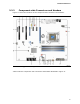
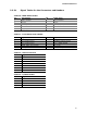

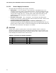
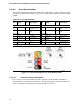
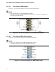
Table Of Contents
- Intel® Desktop Board DP55WG Technical Product Specification
- Revision History
- Preface
- Contents
- 1 Product Description
- 2 Technical Reference
- 3 Overview of BIOS Features
- 4 Error Messages and Beep Codes
- 5 Regulatory Compliance and Battery Disposal Information
Intel Desktop Board DP55WG Technical Product Specification
46
2.2.2.3 Power Supply Connectors
The board has the following power supply connectors:
• Main power – a 2 x 12 connector. This connector is compatible with 2 x 10
connectors previously used on Intel Desktop boards. The board supports the use
of ATX12V power supplies with either 2 x 10 or 2 x 12 main power cables. When
using a power supply with a 2 x 10 main power cable, attach that cable on the
rightmost pins of the main power connector, leaving pins 11, 12, 23, and
24 unconnected.
• Processor core power – a 2 x 4 connector. This connector provides power
directly to the processor voltage regulator and must always be used. Failure to do
so will prevent the board from booting.
• Auxiliary PCI Express graphics power connector (SATA style) – this
connector provides the required additional power when using high power (75 W or
greater) add-in cards in either or both the PCI Express x16 and the PCI Express x8
bus add-in card connectors. See Figure 1 for location.
CAUTION
If high power (75 W or greater) add-in cards are installed in either or both the
Secondary PCI Express x16 and the PCI Express x4 bus add-in card connectors, the
Auxiliary PCI Express graphics power connector must be used. Failure to do so may
cause damage to the board and the add-in cards.
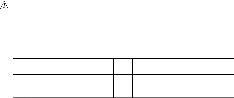
Table 16. Processor Core Power Connector
Pin Signal Name Pin Signal Name
1 Ground 2 +12 V
3 Ground 4 +12 V
5 Ground 6 +12 V
7 Ground 8 +12 V