
Intel Desktop Board DP55WG Technical Product Specification
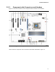


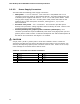
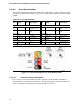
Table Of Contents
- Intel® Desktop Board DP55WG Technical Product Specification
- Revision History
- Preface
- Contents
- 1 Product Description
- 2 Technical Reference
- 3 Overview of BIOS Features
- 4 Error Messages and Beep Codes
- 5 Regulatory Compliance and Battery Disposal Information
Technical Reference
45
2.2.2.2 Add-in Card Connectors
The board has the following add-in card connectors:
• PCI Express 2.0 x16: one PCI Express 2.0 x16 connector supporting simultaneous
transfer speeds up to 8 GB/s of peak bandwidth per direction and up to 16 GB/s
concurrent bandwidth.
• PCI Express 2.0 x8: one PCI Express 2.0 x 8 connector supporting simultaneous
transfer speeds up to 4 GB/s of peak bandwidth per direction and up to 8 GB/s
concurrent bandwidth.
• PCI Express 2.0 x4: one PCI Express 2.0 x4 connector (implemented using a x4
physical connector capable of accepting a x16 card). The x4 interface supports
simultaneous transfer speeds up to 500 MB/s of peak bandwidth per direction and
up to 4 GB/s concurrent bandwidth.
• PCI Express 2.0 x1: two PCI Express 2.0 x1 connectors. The x1 interface
supports simultaneous transfer speeds up to 1 GB/s of peak bandwidth per
direction and up to 2 GB/s concurrent bandwidth.
• PCI Conventional (rev 2.3 compliant) bus: two PCI Conventional bus add-in card
connectors.
Note the following considerations for the PCI Conventional bus connector:
• The PCI Conventional bus connectors are bus master capable.
• SMBus signals are routed to the PCI Conventional bus connectors. This enables
PCI Conventional bus add-in boards with SMBus support to access sensor data on
the desktop board. The specific SMBus signals are as follows:
⎯ The SMBus clock line is connected to pin A40.
⎯ The SMBus data line is connected to pin A41.