Intel® Desktop Board DP55WB Product Guide Order Number: E65064-004
Revision History Revision -001 -002 -003 Revision History First release of the Intel® Desktop Board DP55WB Product Guide Second release of the Intel® Desktop Board DP55WB Product Guide Third release of the Intel® Desktop Board DP55WB Product Guide Date July 2009 December 2009 May 2010 If an FCC declaration of conformity marking is present on the board, the following statement applies: FCC Declaration of Conformity This device complies with Part 15 of the FCC Rules.
Preface This Product Guide gives information about board layout, component installation, BIOS update, and regulatory requirements for Intel® Desktop Board DP55WB. Intended Audience The Product Guide is intended for technically qualified personnel. It is not intended for general audiences. Use Only for Intended Applications All Intel Desktop Boards are evaluated as Information Technology Equipment (I.T.E.
Intel Desktop Board DP55WB Product Guide Terminology The table below gives descriptions of some common terms used in the product guide.
Contents 1 Desktop Board Features Supported Operating Systems..............................................................................10 Desktop Board Components.................................................................................11 Processor..........................................................................................................13 Main Memory.....................................................................................................14 Intel® P55 Express Chipset ..
Intel Desktop Board DP55WB Product Guide Connecting the Processor Fan Heat Sink Cable................................................34 Removing the Processor ..............................................................................34 Installing and Removing System Memory ..............................................................35 Guidelines for Dual Channel Memory Configuration ..........................................35 Two or Four DIMMs ........................................................
Contents B Regulatory Compliance Safety Standards ...............................................................................................67 Place Battery Marking .................................................................................67 European Union Declaration of Conformity Statement..............................................68 Product Ecology Statements ................................................................................69 Recycling Considerations .......................
Intel Desktop Board DP55WB Product Guide Tables 1. 2. 3. 4. 5. 6. 7. 8. 9. 10. 11. 12. 13. 14. 15. 16. 17. 18. 19. 20. 21. viii Feature Summary.......................................................................................... 9 Intel Desktop Board DP55WB Components .......................................................12 LAN Connector LEDs .....................................................................................16 S/PDIF Header Signal Names ...........................................
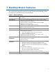
1 Desktop Board Features This chapter briefly describes the features of Intel® Desktop Board DP55WB. Table 1 summarizes the major features of the Desktop Board. Table 1. Feature Summary Form Factor MicroATX (243.84 millimeters [9.60 inches] x 243.84 millimeters [9.
Intel Desktop Board DP55WB Product Guide Table 1.
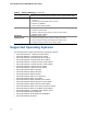
Desktop Board Features Desktop Board Components Figure 1 shows the approximate location of the major components on Intel Desktop Board DP55WB. Figure 1.
Intel Desktop Board DP55WB Product Guide Table 2. Intel Desktop Board DP55WB Components 12 Label Description A PCI bus connector B Front panel audio header C PCI Express 2.0 x1 connector D PCI Express 2.0 x1 connector E PCI Express 2.
Desktop Board Features Online Support For more information on Intel Desktop Board DP55WB consult the following online resources: • Intel Desktop Board DP55WB http://www.intel.com/products/motherboard/DP55WB /index.htm • Desktop Board Support http://support.intel.com/support/motherboards/deskt op/DP55WB • Available configurations for Intel Desktop Board DP55WB http://www.intel.com/products/motherboard/DP55WB /index.htm • Supported processors http://processormatch.intel.
Intel Desktop Board DP55WB Product Guide Main Memory NOTE To be fully compliant with all applicable Intel ® SDRAM memory specifications, the board should be populated with DIMMs that support the Serial Presence Detect (SPD) data structure. If your memory modules do not support SPD, you will see a notification to this effect on the screen at power up. The BIOS will attempt to configure the memory controller for normal operation.
Desktop Board Features Intel® P55 Express Chipset The Intel P55 Express Chipset consists of the Intel P55 Express Platform Controller Hub (PCH). The PCH is the centralized controller for the board’s I/O paths.
Intel Desktop Board DP55WB Product Guide Figure 2. LAN Connector LEDs Table 3. LAN Connector LEDs LED LED Color LED State Indicates A Green Off LAN link is not established On LAN link is established B Blinking LAN activity is occurring N/A Off 10 Mb/s data rate Green On 100 Mb/s data rate Yellow On 1000 Mb/s data rate USB 2.0 Support The Desktop Board provides 14 USB 2.0 ports (eight ports routed to back panel connectors and six ports routed to three onboard headers).
Desktop Board Features Serial ATA Support Intel Desktop Board DP55WB supports six onboard 3.0 Gb/s Serial ATA (SATA) channels via the PCH.
Intel Desktop Board DP55WB Product Guide Security Passwords The BIOS includes security features that restrict whether the BIOS Setup program can be accessed and who can boot the computer. A supervisor password and a user password can be set for the BIOS Setup and for booting the computer, with the following restrictions: • • • The supervisor password gives unrestricted access to view and change all Setup options.
Desktop Board Features Chassis Intrusion The board supports a chassis security feature that detects if the chassis cover has been removed. The security feature uses a mechanical switch on the chassis that can be connected to the chassis intrusion header on the Desktop Board. See Figure 22 for the location of the chassis intrusion header.
Intel Desktop Board DP55WB Product Guide Fan Headers The function/operation of the fans is as follows: • • • • • The fans are on when the computer is in the ACPI S0 state. The fans are off when the computer is in the ACPI S3, S4, or S5 state. Each fan header is wired to a tachometer input of the hardware monitoring and control device. All fan headers support closed-loop fan control that can adjust the fan speed or switch the fan on or off as needed. All fan headers have a +12 V DC connection.
Desktop Board Features The Desktop Board supports the PCI Bus Power Management Interface Specification. Add-in cards that support this specification can participate in power management and can be used to wake the computer. +5 V Standby Power Indicator CAUTION If the AC power has been switched off and the standby power indicator is still lit, disconnect the power cord before installing or removing any devices connected to the board. Failure to do so could damage the board and any attached devices.
Intel Desktop Board DP55WB Product Guide Wake from USB NOTE Wake from USB requires the use of a USB peripheral that supports Wake from USB and an operating system that supports Wake from USB. USB bus activity wakes the computer from an ACPI S1 or S3 state. PME# Signal Wake-up Support When the PME# signal on the PCI bus is asserted, the computer wakes from an ACPI S1, S3, S4, or S5 state.
Desktop Board Features Speaker A speaker is mounted on the Desktop Board. The speaker provides audible error code (beep code) information during the Power-On Self-Test (POST). Refer to Appendix A for a description of the board’s beep codes. Battery A battery on the Desktop Board keeps the values in CMOS RAM and the clock current when the computer is turned off. Go to page 52 for instructions on how to replace the battery. Real-Time Clock The Desktop Board has a time-of-day clock and 100-year calendar.
Intel Desktop Board DP55WB Product Guide 24
2 Installing and Replacing Desktop Board Components This chapter tells you how to: • • • • • • • • • • • • Install the I/O shield Install and remove the Desktop Board Install and remove a processor Install and remove memory Install and remove a PCI Express x16 card Connect Serial ATA cables Connect to the internal headers and connectors Connect to the audio system Connect chassis fan and power supply cables Set the BIOS configuration jumper Clear passwords Replace the battery Before You Begin CAUTIONS The
Intel Desktop Board DP55WB Product Guide Installation Precautions When you install and test the Intel Desktop Board, observe all warnings and cautions in the installation instructions.
Installing and Replacing Desktop Board Components Installing the I/O Shield The Desktop Board comes with an I/O shield. When installed in the chassis, the shield blocks radio frequency transmissions, protects internal components from dust and foreign objects, and promotes correct airflow within the chassis. Install the I/O shield before installing the Desktop Board in the chassis. Place the shield inside the chassis as shown in Figure 4. Press the shield into place so that it fits tightly and securely.
Intel Desktop Board DP55WB Product Guide Installing and Removing the Desktop Board CAUTION Only qualified technical personnel should perform this procedure. Disconnect the computer from its power source before performing the procedures described here. Failure to disconnect the power before you open the computer can result in personal injury or equipment damage. Refer to your chassis manual for instructions on installing and removing the Desktop Board.
Installing and Replacing Desktop Board Components Installing and Removing a Processor Instructions on how to install the processor on the Desktop Board are given below. Installing a Processor CAUTION Before installing or removing a processor, make sure the AC power has been removed by unplugging the power cord from the computer; the standby power LED should not be lit (see Figure 3 on page 21). Failure to do so could damage the processor and the board. To install a processor, follow these instructions: 1.
Intel Desktop Board DP55WB Product Guide 3. Rotate the socket lever to lift the load plate away from the socket (Figure 7, A). Make sure that the load plate is in the fully open position (Figure 7, B) while being careful not to damage adjacent components. Figure 7.
Installing and Replacing Desktop Board Components 4. Remove the protective socket cover from the socket by placing your thumb against the front edge of the cover and resting your index finger on the rear grip (Figure 8, A). Lift the front edge of the socket to disengage the cover from the socket and lift the cover up and away from the socket (Figure 8, B). Do not touch the socket contacts. NOTE Do not discard the socket cover; save it for possible future use.
Intel Desktop Board DP55WB Product Guide 5. Remove the processor from its protective cover. Hold the processor only at the edges, being careful not to touch the bottom of the processor (see Figure 9). NOTE Do not discard the processor cover. Always replace the processor cover if you remove the processor from the socket. Figure 9. Remove the Processor from the Protective Cover 6.
Installing and Replacing Desktop Board Components 7. Lower the load plate over the processor while leaving the socket lever in the open position (Figure 11). Figure 11. Lower the Load Plate 8. Lower the socket lever (Figure 12, B) while making sure that the front edge of the load plate slides under the shoulder screw cap as the lever is lowered (Figure 12, A). Latch the socket lever under the load plate tab (Figure 12, C, D). Figure 12.
Intel Desktop Board DP55WB Product Guide Installing a Processor Fan Heat Sink Intel Desktop Board DP55WB has mounting holes for a processor fan heat sink. For instructions on how to attach the processor fan heat sink to the Desktop Board, refer to the boxed processor manual or boxed thermal solution manual. Connecting the Processor Fan Heat Sink Cable Connect the processor fan heat sink power cable to the 4-pin processor fan header (see Figure 13).
Installing and Replacing Desktop Board Components Installing and Removing System Memory Desktop board DP55WB has four 240-pin DDR3 DIMM sockets arranged as DIMM 0 and DIMM 1 in both Channel A and Channel B. NOTE The Intel P55 Express Chipset requires memory to installed in the Channel A, DIMM 0 slot. Guidelines for Dual Channel Memory Configuration Before installing DIMMs, read and follow these guidelines for dual channel memory configuration.
Intel Desktop Board DP55WB Product Guide Figure 15. Example Dual Channel Memory Configuration with Four DIMMs Three DIMMs If you want to use three DIMMs in a dual-channel configuration, install a matched pair of DIMMs equal in speed and size in DIMM 0 (blue) and DIMM 1 (black) of channel A. Install a DIMM equal in speed and total size of the DIMMs installed in channel A in either DIMM 0 or DIMM 1 of channel B (see Figure 16). Figure 16.
Installing and Replacing Desktop Board Components Installing DIMMs To make sure you have the correct DIMM, place it on the illustration of the DDR3 DIMM in Figure 17. All the notches should match with the DDR3 DIMM. Figure 17.
Intel Desktop Board DP55WB Product Guide To install a DIMM, follow these steps: 1. Observe the precautions in "Before You Begin" on page 25. 2. Turn off all peripheral devices connected to the computer. Turn off the computer and disconnect the AC power cord. 3. Remove the computer’s cover and locate the DIMM sockets (see Figure 18). Figure 18. Installing a DIMM 4. Make sure the clips at either end of the DIMM socket(s) are pushed outward to the open position. 5.
Installing and Replacing Desktop Board Components Removing DIMMs To remove a DIMM, follow these steps: 1. 2. 3. 4. 5. Observe the precautions in "Before You Begin" on page 25. Turn off all peripheral devices connected to the computer. Turn off the computer. Remove the AC power cord from the computer. Remove the computer’s cover. Gently spread the retaining clips at each end of the DIMM socket. The DIMM pops out of the socket. 6.
Intel Desktop Board DP55WB Product Guide Figure 19. Installing a PCI Express x16 Graphics Card Removing a PCI Express x16 Graphics Card Follow these instructions to remove a PCI Express x16 graphics card from a connector: 1. Observe the precautions in "Before You Begin" on page 25. 2. Disconnect the monitor cable from the graphics card back panel connector. 3. Remove the screw (Figure 20, A) that secures the card’s metal bracket to the chassis back panel. 4.
Installing and Replacing Desktop Board Components Figure 20.
Intel Desktop Board DP55WB Product Guide Connecting Serial ATA (SATA) Cables SATA cables support the Serial ATA protocol. Each cable can be used to connect one internal SATA drive to the Desktop Board. For correct cable function: 1. Observe the precautions in “Before You Begin” on page 25. 2. Attach one end of the SATA cable to one of the SATA connectors on the board (Figure 21, A) and attach the other end of the cable to the SATA drive (Figure 21, B). Figure 21.
Installing and Replacing Desktop Board Components Connecting to the Internal Headers Before connecting cables to any of the internal headers, observe the precautions in “Before You Begin” on page 25. Figure 22 shows the location of the internal headers and connectors on Intel Desktop Board DP55WB. Figure 22.
Intel Desktop Board DP55WB Product Guide S/PDIF Header Figure 22, A shows the location of the S/PDIF output header. Table 4 shows the pin assignments and signal names for the S/PDIF connector. Table 4. S/PDIF Header Signal Names Pin Description 1 Ground 2 S/PDIF Out 3 Key (no pin) 4 +5 VDC Front Panel Audio Header The front panel audio header shown in Figure 22, B supports both Intel High Definition (HD) Audio and AC ’97 Audio.
Installing and Replacing Desktop Board Components Chassis Intrusion Header Figure 22, C shows the location of the chassis intrusion header. This header can be connected to a mechanical switch on the chassis to detect if the chassis cover is removed. This switch should be in the open position when the chassis cover is installed and closed when the cover is removed. Table 7 shows the pin assignments and signal names for the chassis intrusion header. Table 7.
Intel Desktop Board DP55WB Product Guide Alternate Front Panel Power LED Header Figure 22, E shows the location of the alternate front panel power LED header. Pins 1 and 3 of this header duplicate the signals on pins 2 and 4 of the front panel header. If your chassis has a three-pin power LED cable, connect it to this header. Table 9 shows the pin assignments for the alternate front panel header. Table 9.
Installing and Replacing Desktop Board Components IEEE 1394a Header Figure 22, G shows the location of the IEEE 1394a header. Table 12 shows the pin assignments and signal names for the IEEE 1394a header. Table 12.
Intel Desktop Board DP55WB Product Guide Connecting Chassis Fan and Power Supply Cables Connecting Chassis Fan Cables Connect chassis fan cables to the chassis fan headers on the Desktop Board. Figure 24 shows the location of the chassis fan headers. Figure 24.
Installing and Replacing Desktop Board Components Connecting Power Supply Cables Figure 25 shows the location of the power connectors. CAUTION Failure to use an appropriate power supply and/or not connecting the 12 V (Figure 25, A) power connector to the Desktop Board may result in damage to the board or the system may not function properly. The 2 x 12 pin main power connector (Figure 25, B) is backwards compatible with ATX12V power supplies with 2 x 10 connectors. Figure 25.
Intel Desktop Board DP55WB Product Guide Setting the BIOS Configuration Jumper NOTE Always turn off the power and unplug the power cord from the computer before moving the jumper. Moving the jumper with the power on may result in unreliable computer operation. Figure 26 shows the location of the Desktop Board’s BIOS configuration jumper block. Figure 26.
Installing and Replacing Desktop Board Components The three-pin BIOS jumper block enables board configuration to be done in the BIOS Setup program. Table 13 shows the jumper settings for the BIOS Setup program modes. Table 13. Jumper Settings for the BIOS Setup Program Modes Jumper Setting Mode Description Normal (default) (1-2) The BIOS uses the current configuration and passwords for booting. Configure (2-3) After the Power-On Self-Test (POST) runs, the BIOS displays the Maintenance Menu.
Intel Desktop Board DP55WB Product Guide 8. Use the arrow keys to select Clear Passwords. Press and Setup displays a pop-up screen requesting that you confirm clearing the password. Select Yes and press . Setup displays the maintenance menu again. 9. Press to save the current values and exit Setup. 10. Turn off the computer. Disconnect the computer’s power cord from the AC power source. 11. Remove the computer cover. 12.
Installing and Replacing Desktop Board Components OBS! Det kan oppstå eksplosjonsfare hvis batteriet skiftes ut med feil type. Brukte batterier bør kastes i henhold til gjeldende miljølovgivning. VIKTIGT! Risk för explosion om batteriet ersätts med felaktig batterityp. Batterier ska kasseras enligt de lokala miljövårdsbestämmelserna. VARO Räjähdysvaara, jos pariston tyyppi on väärä. Paristot on kierrätettävä, jos se on mahdollista.
Intel Desktop Board DP55WB Product Guide UPOZORNÌNÍ V případě výměny baterie za nesprávný druh může dojít k výbuchu. Je-li to možné, baterie by měly být recyklovány. Baterie je třeba zlikvidovat v souladu s místními předpisy o životním prostředí. Προσοχή Υπάρχει κίνδυνος για έκρηξη σε περίπτωση που η μπαταρία αντικατασταθεί από μία λανθασμένου τύπου. Οι μπαταρίες θα πρέπει να ανακυκλώνονται όταν κάτι τέτοιο είναι δυνατό.
Installing and Replacing Desktop Board Components UPOZORNENIE Ak batériu vymeníte za nesprávny typ, hrozí nebezpečenstvo jej výbuchu. Batérie by sa mali podľa možnosti vždy recyklovať. Likvidácia použitých batérií sa musí vykonávať v súlade s miestnymi predpismi na ochranu životného prostredia. POZOR Zamenjava baterije z baterijo drugačnega tipa lahko povzroči eksplozijo. Če je mogoče, baterije reciklirajte. Rabljene baterije zavrzite v skladu z lokalnimi okoljevarstvenimi predpisi. .
Intel Desktop Board DP55WB Product Guide 56
Installing and Replacing Desktop Board Components To replace the battery, follow these steps: 1. Observe the precautions in "Before You Begin" (see page 25). 2. Turn off all peripheral devices connected to the computer. Disconnect the computer’s power cord from the AC power source (wall outlet or power adapter). 3. Remove the computer cover. 4. Locate the battery on the board (see Figure 27). 5. With a medium flat-bladed screwdriver, gently pry the battery free from its connector.
Intel Desktop Board DP55WB Product Guide 58
3 Updating the BIOS The BIOS Setup program can be used to view and change the BIOS settings for the computer. You can access the BIOS Setup program by pressing the key after the Power-On Self-Test (POST) memory test begins and before the operating system boot begins. This chapter tells you how to update the BIOS by either using the Intel Express BIOS Update utility or the Iflash Memory Update utility, and how to recover the BIOS if an update fails.
Intel Desktop Board DP55WB Product Guide Updating the BIOS with the ISO Image BIOS Update File or the Iflash Memory Update Utility You can use the information in this section to update the BIOS using either the Iflash Memory Update Utility or the ISO Image BIOS update file. Obtaining the BIOS Update File You can update to a new version of the BIOS by using the ISO Image BIOS update file (recommended), or Iflash BIOS update file.
Updating the BIOS Updating the BIOS with the ISO Image BIOS Update File The ISO Image BIOS update allows for the update of an Intel® Desktop Board BIOS to the latest production release regardless of the operating system installed on the computer's hard drive and without the need to remove the BIOS configuration jumper. It requires a blank CD-R, a read/writeable CD drive, and software capable of uncompressing and writing the ISO image file to CD.
Intel Desktop Board DP55WB Product Guide Updating the BIOS with the Iflash Memory Update Utility With the Iflash Memory update utility you can update the system BIOS from a bootable CD-ROM, bootable USB flash drive, or other bootable USB media. The utility available on the Intel World Wide Web site provides a simple method for creating a bootable CD-ROM that will automatically update your BIOS.
4 Configuring for RAID Using Intel® Matrix Storage Technology NOTE Intel Matrix Storage Technology requires Microsoft Windows 7, Microsoft Windows Vista, or Microsoft Windows XP operating system and SATA hard drives. Configuring the BIOS 1. Assemble your system and attach two or more SATA hard drives to the SATA connectors. 2. Enter system BIOS Setup by pressing after the Power-On-Self-Test (POST) memory tests begin. 3.
Intel Desktop Board DP55WB Product Guide Loading the Intel Matrix Storage Technology RAID Drivers and Software (Required for Microsoft Windows XP Installation) 1. Begin Windows Setup by booting from the Windows installation CD. 2. At the beginning of Windows Setup, press to install a third-party SCSI or RAID driver. When prompted, insert the diskette that contains the Intel Matrix Storage Technology RAID Driver in a USB floppy disk drive. Refer to http://support.microsoft.
A Error Messages and Indicators Intel Desktop Board DP55WB reports POST errors in two ways: • • By sounding a beep code and blinking the front panel power LED By displaying an error message on the monitor BIOS Error Codes Whenever a recoverable error occurs during POST, the BIOS causes the board’s speaker to beep and the front panel power LED to blink an error message indicating the problem (see Table 14). Table 14. BIOS Beep Codes Type Pattern Processor One 0.
Intel Desktop Board DP55WB Product Guide BIOS Error Messages When a recoverable error occurs during the POST, the BIOS displays an error message describing the problem. Table 16 gives an explanation of the BIOS error messages. Table 16. BIOS Error Messages 66 Error Message Explanation PROCESSOR_THERMAL_TRIP_ERROR Processor was previously shutdown due to a thermal event (overheating). CMOS_BATTERY_ERROR The firmware has detected that a CMOS battery failure occurred.
B Regulatory Compliance This appendix contains the following regulatory compliance information for Intel Desktop Board DP55WB: • • • • • Safety standards European Union Declaration of Conformity statement Product Ecology statements Electromagnetic Compatibility (EMC) regulations Product certifications Safety Standards Intel Desktop Board DP55WB complies with the safety standards stated in Table 17 when correctly installed in a compatible host system. Table 17.
Intel Desktop Board DP55WB Product Guide European Union Declaration of Conformity Statement We, Intel Corporation, declare under our sole responsibility that the product Intel® Desktop Board DP55WB is in conformity with all applicable essential requirements necessary for CE marking, following the provisions of the European Council Directives 2004/108/EC (EMC Directive) and 2006/95/EC (Low Voltage Directive).
Regulatory Compliance Lietuvių Šis produktas atitinka Europos direktyvų 2004/108/EC ir 2006/95/EC nuostatas. Malti Dan il-prodott hu konformi mal-provvedimenti tad-Direttivi Ewropej 2004/108/EC u 2006/95/EC. Norsk Dette produktet er i henhold til bestemmelsene i det europeiske direktivet 2004/108/EC & 2006/95/EC. Polski Niniejszy produkt jest zgodny z postanowieniami Dyrektyw Unii Europejskiej 2004/108/EC i 2006/95/EC.
Intel Desktop Board DP55WB Product Guide Deutsch Als Teil von Intels Engagement für den Umweltschutz hat das Unternehmen das Intel Produkt-Recyclingprogramm implementiert, das Einzelhandelskunden von Intel Markenprodukten ermöglicht, gebrauchte Produkte an ausgewählte Standorte für ordnungsgemäßes Recycling zurückzugeben. Details zu diesem Programm, einschließlich der darin eingeschlossenen Produkte, verfügbaren Standorte, Versandanweisungen, Bedingungen usw., finden Sie auf der http://www.intel.
Regulatory Compliance Portuguese Como parte deste compromisso com o respeito ao ambiente, a Intel implementou o Programa de Reciclagem de Produtos para que os consumidores finais possam enviar produtos Intel usados para locais selecionados, onde esses produtos são reciclados de maneira adequada. Consulte o site http://www.intel.
Intel Desktop Board DP55WB Product Guide Lead-free 2LI/Pb-free 2LI Board The electronics industry is transitioning to European Union (EU) Restriction of Hazardous Substances (RoHS)-compliant products. The RoHS legislation restricts the use of six materials. One of these restricted materials is lead. Lead is the most common and problematic of the RoHS restricted materials. There are exemptions in RoHS that allow the use of lead in some very limited locations in electronic products.
Regulatory Compliance Table 18. Lead-Free Second Level Interconnect Marks Description Mark This symbol is used to identify electrical and electronic assemblies and components in which the Pb concentration level in the Desktop Board substrate and the solder connections from the board to the components (second-level interconnect) is not greater than 0.1% by weight (1000 ppm).
Intel Desktop Board DP55WB Product Guide China RoHS “China RoHS” is the term used by industry generally to describe legislation implemented by the Ministry of Information Industry (MII) in the People's Republic of China for the control of pollution by electronic information products (EIP). The official title of the China RoHS regulation is “Management Methods for Controlling Pollution by Electronic Information Products.” China RoHS bans the same substances and has the same limits as EU RoHS.
Regulatory Compliance The China MII stipulates that a material Self Declaration Table (SDT) must be included in a product’s user documentation. The SDT for Intel Desktop Board DP55WB is shown in Figure 28. Figure 28.
Intel Desktop Board DP55WB Product Guide EMC Regulations Intel Desktop Board DP55WB complies with the EMC regulations stated in Table 20 when correctly installed in a compatible host system. Table 20. EMC Regulations Regulation (Class B) Title FCC 47 CFR Part 15, Subpart B Title 47 of the Code of Federal Regulations, Part 15, Subpart B, Radio Frequency Devices. (USA) ICES-003 Issue 4 Interference-Causing Equipment Standard, Digital Apparatus.
Regulatory Compliance Korean Class B statement translation: This is household equipment that is certified to comply with EMC requirements. You may use this equipment in residential environments and other non-residential environments. Ensure Electromagnetic Compatibility (EMC) Compliance Before computer integration, make sure that the power supply and other modules or peripherals, as applicable, have passed Class B EMC testing and are marked accordingly.
Intel Desktop Board DP55WB Product Guide Product Certifications Board-Level Certification Markings Intel Desktop Board DP55WB has the product certification markings shown in Table 21. Table 21. Product Certification Markings Description UL joint US/Canada Recognized Component mark. Includes adjacent UL file number for Intel Desktop Boards: E210882. Mark FCC Declaration of Conformity logo mark for Class B equipment. Includes Intel name and DP55WB model designation. CE mark.
Regulatory Compliance Chassis and Component Certifications Ensure that the chassis and certain components; such as the power supply, peripheral drives, wiring, and cables; are components certified for the country or market where used. Agency certification marks on the product are proof of certification. Typical product certifications include: In Europe The CE marking signifies compliance with all applicable European requirements.
Intel Desktop Board DP55WB Product Guide 80