Intel® Desktop Board DP45SG Product Guide Order Number: E30016-001
Revision History Revision -001 Revision History First release of the Intel® Desktop Board DP45SG Product Guide Date June 2008 If an FCC declaration of conformity marking is present on the board, the following statement applies: FCC Declaration of Conformity This device complies with Part 15 of the FCC Rules.
Preface This Product Guide gives information about board layout, component installation, BIOS update, and regulatory requirements for Intel® Desktop Board DP45SG. Intended Audience The Product Guide is intended for technically qualified personnel. It is not intended for general audiences. Use Only for Intended Applications All Intel Desktop Boards are evaluated as Information Technology Equipment (I.T.E.
Intel Desktop Board DP45SG Product Guide Conventions The following conventions are used in this manual: CAUTION Cautions warn the user about how to prevent damage to hardware or loss of data. NOTE Notes call attention to important information. Terminology The table below gives descriptions of some common terms used in the product guide.
Contents 1 Desktop Board Features Desktop Board Components.................................................................................11 Processor..........................................................................................................13 Main Memory.....................................................................................................13 Intel® P45 Express Chipset ..................................................................................14 Audio Subsystem .........
Intel Desktop Board DP45SG Product Guide Installing and Removing a Processor .....................................................................29 Installing a Processor ..................................................................................29 Installing the Processor Fan Heat Sink ...........................................................33 Connecting the Processor Fan Heat Sink Cable................................................33 Removing the Processor ...................................
Contents 4 Configuring for RAID Using Intel® Matrix Storage Technology (Intel® MST) Configuring the BIOS..........................................................................................65 Creating Your RAID Set.......................................................................................65 Loading the Intel Matrix Storage Technology RAID Drivers and Software for Microsoft Windows* XP..................................................................................
Intel Desktop Board DP45SG Product Guide 14. 15. 16. 17. 18. 19. 20. 21. 22. 23. 24. 25. 26. 27. 28. 29. Dual Channel Memory Configuration with Two DIMMs ........................................35 Dual Channel Memory Configuration with Four DIMMs........................................36 Dual Channel Memory Configuration with Three DIMMs ......................................36 Use DDR3 DIMMs .........................................................................................37 Installing a DIMM ....
1 Desktop Board Features This chapter briefly describes the features of Intel® Desktop Board DP45SG. Table 1 summarizes the major features of the Desktop Board. Table 1. Feature Summary Form Factor ATX (294.64 millimeters [11.60 inches] x 243.84 millimeters [9.60 inches]) Processor Support for an Intel® processor in the LGA775 package Main Memory • Four 240-pin, DDR3 1.
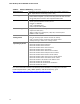
Intel Desktop Board DP45SG Product Guide Table 1.
Desktop Board Features Desktop Board Components Figure 1 shows the approximate location of the major components on Intel Desktop Board DP45SG. Figure 1.
Intel Desktop Board DP45SG Product Guide Table 2. Intel Desktop Board DP45SG Components 12 Label Description A PCI bus connector 3 B S/PDIF connector C PCI bus connector 2 D PCI bus connector 1 E PCI Express 2.0 x16 secondary connector F PCI Express 1.1 x1 connector 2 G IEEE 1394a header H PCI Express 1.1 x1 connector I PCI Express 2.
Desktop Board Features Processor CAUTION Failure to use an appropriate power supply and/or not connecting the 12 V (2 x 2 pin) power connector to the Desktop Board may result in damage to the board, or the system may not function properly. Intel Desktop Board DP45SG supports an Intel processor in the LGA775 package. Processors are not included with the Desktop Board and must be purchased separately. The processor connects to the Desktop Board through the LGA775 socket.
Intel Desktop Board DP45SG Product Guide Go to the following locations for more information about: • • • SDRAM specifications, http://www.intel.com/technology/memory/ Installing memory, page 35 in Chapter 2 Tested memory, http://www.cmtlabs.com/mbsearch.
Desktop Board Features LAN Subsystem The LAN subsystem includes: • • • Intel ICH10R Intel 82567LF Gigabit (10/100/1000 Mb/s) Ethernet LAN controller RJ-45 LAN connector with integrated status LEDs The subsystem features: • CSMA/CD protocol engine • LAN connect interface between ICH10R and the LAN controller • PCI Express power management For information about LAN software and drivers go to http://support.intel.
Intel Desktop Board DP45SG Product Guide USB 2.0 Support The Desktop Board supports up to 12 USB 2.0 ports (six ports routed to back panel connectors and six ports routed to three onboard headers) via the ICH10R. USB 2.0 ports are backward compatible with USB 1.1 devices. USB 1.1 devices will function normally at USB 1.1 speeds. USB 2.0 support requires both an operating system and drivers that fully support USB 2.0 transfer rates. Disabling Hi-Speed USB in the BIOS reverts all USB 2.0 ports to USB 1.
Desktop Board Features Legacy I/O Intel Desktop Board DP45SG includes an I/O controller that provides the following legacy I/O features: • • • • • One serial port via an onboard header Consumer Infrared (CIR) support Low pin count (LPC) interface Intelligent power management, including a programmable wake up event interface PCI power management support Expandability Intel Desktop Board DP45SG provides the following expansion capability: • • • Two PCI Express 2.
Intel Desktop Board DP45SG Product Guide Security Passwords The BIOS includes security features that restrict whether the BIOS Setup program can be accessed and who can boot the computer. A supervisor password and a user password can be set for the BIOS Setup and for booting the computer, with the following restrictions: • • • The supervisor password gives unrestricted access to view and change all Setup options.
Desktop Board Features Chassis Intrusion The board supports a chassis security feature that detects if the chassis cover has been removed. The security feature uses a mechanical switch on the chassis that can be connected to the chassis intrusion header on the Desktop Board. See Figure 23 for the location of the chassis intrusion header.
Intel Desktop Board DP45SG Product Guide Fan Headers The function/operation of the fans is as follows: • • • • • The fans are on when the computer is in the ACPI S0 state. The fans are off when the computer is in the ACPI S3, S4, or S5 state. Each fan header is wired to a tachometer input of the hardware monitoring and control device. All fan headers support closed-loop fan control that can adjust the fan speed or switch the fan on or off as needed. All fan headers have a +12 V DC connection.
Desktop Board Features The Desktop Board supports the PCI Bus Power Management Interface Specification. Add-in cards that support this specification can participate in power management and can be used to wake the computer. +5 V Standby Power Indicator CAUTION If the AC power has been switched off and the standby power indicator is still lit, disconnect the power cord before installing or removing any devices connected to the board. Failure to do so could damage the board and any attached devices.
Intel Desktop Board DP45SG Product Guide Wake from USB NOTE Wake from USB requires the use of a USB peripheral that supports Wake from USB and an operating system that supports Wake from USB. USB bus activity wakes the computer from an ACPI S3 state. PME# Signal Wake-up Support When the PME# signal on the PCI bus is asserted, the computer wakes from an ACPI S1, S3, S4, or S5 state.
Desktop Board Features Real-Time Clock The Desktop Board has a time-of-day clock and 100-year calendar. The battery on the Desktop Board keeps the clock current when the computer is turned off.
Intel Desktop Board DP45SG Product Guide 24
2 Installing and Replacing Desktop Board Components This chapter tells you how to: • • • • • • • • • • • • • Install the I/O shield Install and remove the Desktop Board Install and remove a processor Install the ICH heat sink decorative cover (optional) Install and remove memory Install and remove PCI Express x16 cards Connect the Serial ATA cables Connect to the internal headers and connectors Connect to the audio system Connect chassis fan and power supply cables Set the BIOS configuration jumper Clear p
Intel Desktop Board DP45SG Product Guide Installation Precautions When you install and test the Intel Desktop Board, observe all warnings and cautions in the installation instructions.
Installing and Replacing Desktop Board Components Installing the I/O Shield The Desktop Board comes with an I/O shield. When installed in the chassis, the shield blocks radio frequency transmissions, protects internal components from dust and foreign objects, and promotes correct airflow within the chassis. Install the I/O shield before installing the Desktop Board in the chassis. Place the shield inside the chassis as shown in Figure 4. Press the shield into place so that it fits tightly and securely.
Intel Desktop Board DP45SG Product Guide Installing and Removing the Desktop Board CAUTION Only qualified technical personnel should perform this procedure. Disconnect the computer from its power source before performing the procedures described here. Failure to disconnect the power before you open the computer can result in personal injury or equipment damage. Refer to your chassis manual for instructions on installing and removing the Desktop Board.
Installing and Replacing Desktop Board Components Installing and Removing a Processor Instructions on how to install the processor on the Desktop Board are given below. Installing a Processor CAUTION Before installing or removing a processor, make sure the AC power has been removed by unplugging the power cord from the computer; the standby power LED should not be lit (see Figure 3 on page 21). Failure to do so could damage the processor and the board. To install a processor, follow these instructions: 1.
Intel Desktop Board DP45SG Product Guide 3. Lift the load plate (Figure 7, A). Do not touch the socket contacts (Figure 7, B). Figure 7. Lift the Load Plate 4. Remove the plastic protective socket cover from the load plate (Figure 8). Do not discard the protective socket cover. Always replace the socket cover if the processor is removed from the socket. Figure 8.
Installing and Replacing Desktop Board Components 5. Remove the processor from the protective processor cover. Hold the processor only at the edges, being careful not to touch the bottom of the processor (see Figure 9). Do not discard the protective processor cover. Always replace the processor cover if the processor is removed from the socket. Figure 9. Remove the Processor from the Protective Processor Cover 6. Hold the processor with your thumb and index fingers oriented as shown in Figure 10.
Intel Desktop Board DP45SG Product Guide 7. Pressing down on the load plate (Figure 11, A), close and engage the socket lever (Figure 11, B). Figure 11.
Installing and Replacing Desktop Board Components Installing the Processor Fan Heat Sink Intel Desktop Board DP45SG has mounting holes for a processor fan heat sink. For instructions on how to attach the processor fan heat sink to the Desktop Board, refer to the boxed processor manual. Connecting the Processor Fan Heat Sink Cable Connect the processor fan heat sink cable to the 4-pin processor fan header (see Figure 12).
Intel Desktop Board DP45SG Product Guide Removing the Processor For instructions on how to remove the processor fan heat sink and processor, refer to the processor installation manual. Installing the ICH Heat Sink Decorative Cover (Optional) To install the ICH heat sink decorative cover, follow these instructions: 1. Observe the precautions in "Before You Begin" on page 25. 2. Remove the paper covering the adhesive strip on the bottom of the heat sink cover (Figure 13, A). 3.
Installing and Replacing Desktop Board Components Installing and Removing Memory NOTE To be fully compliant with all applicable Intel SDRAM memory specifications, the board requires DIMMs that support the Serial Presence Detect (SPD) data structure. Intel Desktop board DP45SG has four 240-pin DDR3 DIMM sockets arranged as DIMM 0 and DIMM 1 in both Channel A and Channel B. NOTE Regardless of the memory configuration used (dual or single channel), Channel A, DIMM 0 must always be populated.
Intel Desktop Board DP45SG Product Guide If additional memory is to be used, install another matched pair of DIMMs in DIMM 1 (black) in channels A and B (see Figure 15). Figure 15. Dual Channel Memory Configuration with Four DIMMs Three DIMMs If you want to use three DIMMs in a dual-channel configuration, install a matched pair of DIMMs equal in speed and size in DIMM 0 (blue) and DIMM 1 (black) of channel A.
Installing and Replacing Desktop Board Components Installing DIMMs To make sure you have the correct DIMM, place it on the illustration of the DDR3 DIMM in Figure 17. All the notches should match with the DDR3 DIMM. Figure 17.
Intel Desktop Board DP45SG Product Guide To install a DIMM, follow these steps: 1. Observe the precautions in "Before You Begin" on page 25. 2. Turn off all peripheral devices connected to the computer. Turn off the computer and disconnect the AC power cord. 3. Remove the computer’s cover and locate the DIMM sockets (see Figure 18). Figure 18. Installing a DIMM 4. Make sure the clips at either end of the DIMM socket(s) are pushed outward to the open position. 5.
Installing and Replacing Desktop Board Components Removing DIMMs To remove a DIMM, follow these steps: 1. 2. 3. 4. 5. Observe the precautions in "Before You Begin" on page 25. Turn off all peripheral devices connected to the computer. Turn off the computer. Remove the AC power cord from the computer. Remove the computer’s cover. Gently spread the retaining clips at each end of the DIMM socket. The DIMM pops out of the socket. 6.
Intel Desktop Board DP45SG Product Guide Installing and Removing a PCI Express x16 Card CAUTION When installing a PCI Express card on the Desktop Board, ensure that the card is fully seated in the PCI Express connector before you power on the system. If the card is not fully seated in the connector, an electrical short may result across the connector pins. Depending on the over-current protection of the power supply, certain Desktop Board components and/or traces may be damaged.
Installing and Replacing Desktop Board Components Installing a PCI Express x16 Card Follow these instructions to install any PCI Express x16 card: 1. Observe the precautions in "Before You Begin" on page 25. 2. Place the card in a PCI Express x16 connector (Figure 20, A) and press down on the card until it is completely seated in the connector and the card retention notch on the card snaps into place around the retention mechanism pin on the connector. 3.
Intel Desktop Board DP45SG Product Guide Removing a PCI Express x16 Card Follow these instructions to remove a PCI Express x16 card from a connector: 1. Observe the precautions in "Before You Begin" on page 25. 2. Remove the screw (Figure 21, A) that secures the card’s metal bracket to the chassis back panel. 3. Push the card ejector lever down using the tip of a pencil or similar tool (Figure 21, B) in the notch. This will release the card from the connector (C). 4. Pull the card straight up. Figure 21.
Installing and Replacing Desktop Board Components Connecting the Serial ATA (SATA) Cables SATA cables support the Serial ATA protocol. Each cable can be used to connect one internal SATA drive to the Desktop Board. For correct cable function: 1. Observe the precaution in “Before You Begin” on page 25. 2. Attach one end of the SATA cable to one of the SATA connectors on the board (Figure 22, A) and attach the other end of the cable to the SATA drive (Figure 22, B). Figure 22.
Intel Desktop Board DP45SG Product Guide Connecting to the Internal Headers and Connectors Before connecting cables to any of the internal headers or connectors, observe the precautions in “Before You Begin” on page 25. Figure 23 shows the location of the internal headers and connectors on Intel Desktop Board DP45SG.
Installing and Replacing Desktop Board Components S/PDIF Connector Figure 23, A shows the location of the S/PDIF connector. This connector can be used with HDMI video cards that do not work with the HD Audio Link header (see Figure 23, B). Table 4 shows the pin assignments and signal names for the S/PDIF connector. Table 4. S/PDIF Connector Signal Names Pin Description 1 Vcc 2 S/PDIF Out 3 Ground Front Panel Audio Header Figure 23, B shows the location of the front panel audio header.
Intel Desktop Board DP45SG Product Guide IEEE 1394a Header Figure 23, C shows the location of the IEEE 1394a header. Table 7 shows the pin assignments and signal names for the IEEE 1394a header. Table 7.
Installing and Replacing Desktop Board Components Table 9. Back Panel CIR Header Emitter (Output) Header Signal Names Pin Signal Name Pin Signal Name 1 Emitter Out 1 2 Emitter Out 2 3 Ground 4 Key (no pin) 5 Jack Detect 1 6 Jack Detect 2 Chassis Intrusion Header Figure 23, F shows the location of the chassis intrusion header. This header can be connected to a mechanical switch on the chassis to detect if the chassis cover is removed.
Intel Desktop Board DP45SG Product Guide Alternate Front Panel Power LED Header Figure 23, G shows the location of the alternate front panel power LED header. Pins 1 and 3 of this header duplicate the signals on pins 2 and 4 of the front panel header. If your chassis has a three-pin power LED cable, connect it to this header. Table 12 shows the pin assignments and signal names for the alternate front panel power LED header. Table 12.
Installing and Replacing Desktop Board Components USB 2.0 Headers Figure 23, J shows the location of the USB 2.0 headers. Table 14 shows the pin assignments and signal names for each USB 2.0 header. Each USB header can be used to connect two USB devices. Table 14. USB 2.0 Header Signal Names USB Port A Pin 1 3 5 7 9 USB Port B Signal Name Power (+5 V) DD+ Ground Key Pin 2 4 6 8 10 Signal Name Power (+5 V) DD+ Ground No Connection Note: USB ports may be assigned as needed.
Intel Desktop Board DP45SG Product Guide Connecting to the Flexible Audio System After installing the IDT* audio driver from the Intel® Express Installer DVD-ROM, the multi-channel audio feature can be enabled. Figure 24 shows the back panel audio connectors. The default connector assignments are shown in the table.
Installing and Replacing Desktop Board Components Connecting Chassis Fan and Power Supply Cables Connecting Chassis Fan Cables Connect chassis fan cables to the 3-pin and 4-pin chassis fan headers on the Desktop Board. Figure 25 shows the location of the chassis fan headers. Figure 25.
Intel Desktop Board DP45SG Product Guide Connecting Power Supply Cables CAUTION Failure to use an appropriate power supply and/or not connecting the 12 V (2 x 2 pin) power connector to the Desktop Board may result in damage to the board or the system may not function properly. The 2 x 12 pin main power connector on the Desktop Board is backwards compatible with ATX12V power supplies with 2 x 10 connectors.
Installing and Replacing Desktop Board Components Setting the BIOS Configuration Jumper NOTE Always turn off the power and unplug the power cord from the computer before moving the jumper. Moving the jumper with the power on may result in unreliable computer operation. Figure 27 shows the location of the Desktop Board’s BIOS configuration jumper block. Figure 27.
Intel Desktop Board DP45SG Product Guide Table 16. Jumper Settings for the BIOS Setup Program Modes Jumper Setting Mode Description Normal (default) (1-2) The BIOS uses the current configuration and passwords for booting. Configure (2-3) After the Power-On Self-Test (POST) runs, the BIOS displays the Maintenance Menu. Use this menu to clear passwords. Recovery (None) The BIOS recovers data in the event of a failed BIOS update.
Installing and Replacing Desktop Board Components 10. Turn off the computer. Disconnect the computer’s power cord from the AC power source. 11. Remove the computer cover. 12. To restore normal operation, place the jumper on pins 1-2 as shown below. 13. Replace the cover, plug in the computer, and turn on the computer. Replacing the Battery A coin-cell battery (CR2032) powers the real-time clock and CMOS memory.
Intel Desktop Board DP45SG Product Guide VIKTIGT! Risk för explosion om batteriet ersätts med felaktig batterityp. Batterier ska kasseras enligt de lokala miljövårdsbestämmelserna. VARO Räjähdysvaara, jos pariston tyyppi on väärä. Paristot on kierrätettävä, jos se on mahdollista. Käytetyt paristot on hävitettävä paikallisten ympäristömääräysten mukaisesti. VORSICHT Bei falschem Einsetzen einer neuen Batterie besteht Explosionsgefahr.
Installing and Replacing Desktop Board Components UPOZORNÌNÍ V případě výměny baterie za nesprávný druh může dojít k výbuchu. Je-li to možné, baterie by měly být recyklovány. Baterie je třeba zlikvidovat v souladu s místními předpisy o životním prostředí. Προσοχή Υπάρχει κίνδυνος για έκρηξη σε περίπτωση που η μπαταρία αντικατασταθεί από μία λανθασμένου τύπου. Οι μπαταρίες θα πρέπει να ανακυκλώνονται όταν κάτι τέτοιο είναι δυνατό.
Intel Desktop Board DP45SG Product Guide UPOZORNENIE Ak batériu vymeníte za nesprávny typ, hrozí nebezpečenstvo jej výbuchu. Batérie by sa mali podľa možnosti vždy recyklovať. Likvidácia použitých batérií sa musí vykonávať v súlade s miestnymi predpismi na ochranu životného prostredia. POZOR Zamenjava baterije z baterijo drugačnega tipa lahko povzroči eksplozijo. Če je mogoče, baterije reciklirajte. Rabljene baterije zavrzite v skladu z lokalnimi okoljevarstvenimi predpisi. .
Installing and Replacing Desktop Board Components 59
Intel Desktop Board DP45SG Product Guide To replace the battery, follow these steps: 1. Observe the precautions in "Before You Begin" (see page 25). 2. Turn off all peripheral devices connected to the computer. Disconnect the computer’s power cord from the AC power source (wall outlet or power adapter). 3. Remove the computer cover. 4. Locate the battery on the board (see Figure 28). 5. With a medium flat-bladed screwdriver, gently pry the battery free from its connector.
3 Updating the BIOS The BIOS Setup program can be used to view and change the BIOS settings for the computer. You can access the BIOS Setup program by pressing the key after the Power-On Self-Test (POST) memory test begins and before the operating system boot begins. This chapter tells you how to update the BIOS by either using the Intel Express BIOS Update utility or the Iflash Memory Update utility, and how to recover the BIOS if an update fails.
Intel Desktop Board DP45SG Product Guide Updating the BIOS with the ISO Image BIOS Update File or the Iflash Memory Update Utility You can use the information in this section to update the BIOS using either the Iflash Memory Update Utility or the ISO Image BIOS update file. Obtaining the BIOS Update File You can update to a new version of the BIOS by using the ISO Image BIOS update file (recommended), or Iflash BIOS update file.
Updating the BIOS CAUTION Do not interrupt the process or the system may not function properly. Follow these instructions to upgrade the BIOS using the ISO Image BIOS file: 1. Download the ISO Image BIOS file. 2. Using software capable of uncompressing and writing an ISO image file to CD, burn the data to a blank CD. NOTE Copying the ISO Image BIOS file to CD will not work. The completed CD should contain multiple files and a directory. 3.
Intel Desktop Board DP45SG Product Guide CAUTION Do not interrupt the process or the system may not function properly. 1. Uncompress the BIOS update file and copy the .BIO file, IFLASH.EXE, and .ITK file (optional) to a bootable USB flash drive or other bootable USB media. 2. Configure the BIOS or use the F10 option during POST to boot to the USB device. 3. Manually run the IFLASH.EXE file from the USB device and manually update the BIOS.
4 Configuring for RAID Using Intel® Matrix Storage Technology (Intel® MST) NOTE Intel Matrix Storage Technology requires Microsoft Windows Vista or Microsoft Windows XP operating system and SATA hard drives. Configuring the BIOS 1. Assemble your system and attach two or more SATA hard drives to the SATA connectors. 2. Enter system BIOS Setup by pressing after the Power-On-Self-Test (POST) memory tests begin. 3. Go to Advanced Drive Configuration Configure SATA as; ensure that RAID is selected. 4.
Intel Desktop Board DP45SG Product Guide Loading the Intel Matrix Storage Technology RAID Drivers and Software for Microsoft Windows* XP NOTE You wll not be required to perform these steps if you will be using the Microsoft Windows Vista operating system as the ICH10R driver is supported natively. 1. Begin Windows Setup by booting from the Windows installation CD. 2. At the beginning of Windows Setup, press to install a third-party SCSI or RAID driver.
5 Configuring for Intel® Rapid Recover Technology (Intel® RRT) Intel Rapid Recover technology utilizes RAID 1 (mirroring) functionality to copy data from a designated master drive to a designated recovery drive. The master and recovery drives must span 100 percent of the available hard drive space of an array, and only one recovery volume can be present on a system. You can select whether you want the master drive data to be copied to the recovery drive continuously or on request.
Intel Desktop Board DP45SG Product Guide Creating a Recovery Volume A recovery volume consists of two disks – a master disk and a recovery disk. A recovery volume can be created with either the RAID Option ROM (OROM) or the Intel® Matrix Storage Console application. Creating a Recovery Volume Using the RAID Option ROM To create a recovery volume using the RAID OROM, complete the following steps: 1. Enter the RAID OROM by pressing the and keys simultaneously when prompted during system POST. 2.
Configuring for Intel® Rapid Recover Technology 6. Select the Update policy – Continuous update or Update on request. 7. Select Finish to complete the creation of the recovery volume. The system will synchronize the master disk with the recovery disk once after the creation of the recovery volume. Disk Synchronization Mode There are two modes of updating or synchronizing the recovery disk with the master disk – either continuous update or manual update.
Intel Desktop Board DP45SG Product Guide To un-mount the recovery disk, complete the following steps: 1. In the Advanced mode, right-click on the recovery volume name. 2. Select Access Recovery Drive Files. 3. Select OK on the information dialog box. The recovery disk is now un-mounted and reappears in Intel Matrix Storage Console.
A Error Messages and Indicators Intel Desktop Board DP45SG reports POST errors in two ways: • • By sounding a beep code By displaying an error message on the monitor BIOS Beep Codes The BIOS also issues a beep code (one long tone followed by two short tones) during POST if the video configuration fails (a faulty video card or no card installed) or if an external ROM module does not properly checksum to zero. Table 17 lists the BIOS codes. Table 17.
Intel Desktop Board DP45SG Product Guide 72
B Regulatory Compliance This appendix contains the following regulatory compliance information for Intel Desktop Board DP45SG: • • • • • Safety standards European Union Declaration of Conformity statement Product Ecology statements Electromagnetic Compatibility (EMC) regulations Product certifications Safety Standards Intel Desktop Board DP45SG complies with the safety standards stated in Table 19 when correctly installed in a compatible host system. Table 19.
Intel Desktop Board DP45SG Product Guide European Union Declaration of Conformity Statement We, Intel Corporation, declare under our sole responsibility that the product Intel® Desktop Board DP45SG is in conformity with all applicable essential requirements necessary for CE marking, following the provisions of the European Council Directives 2004/108/EC (EMC Directive) and 2006/95/EC (Low Voltage Directive).
Regulatory Compliance Lietuvių Šis produktas atitinka Europos direktyvų 2004/108/EC ir 2006/95/EC nuostatas. Malti Dan il-prodott hu konformi mal-provvedimenti tad-Direttivi Ewropej 2004/108/EC u 2006/95/EC. Norsk Dette produktet er i henhold til bestemmelsene i det europeiske direktivet 2004/108/EC & 2006/95/EC. Polski Niniejszy produkt jest zgodny z postanowieniami Dyrektyw Unii Europejskiej 2004/108/EC i 2006/95/EC.
Intel Desktop Board DP45SG Product Guide Deutsch Als Teil von Intels Engagement für den Umweltschutz hat das Unternehmen das Intel Produkt-Recyclingprogramm implementiert, das Einzelhandelskunden von Intel Markenprodukten ermöglicht, gebrauchte Produkte an ausgewählte Standorte für ordnungsgemäßes Recycling zurückzugeben. Details zu diesem Programm, einschließlich der darin eingeschlossenen Produkte, verfügbaren Standorte, Versandanweisungen, Bedingungen usw., finden Sie auf der http://www.intel.
Regulatory Compliance Portuguese Como parte deste compromisso com o respeito ao ambiente, a Intel implementou o Programa de Reciclagem de Produtos para que os consumidores finais possam enviar produtos Intel usados para locais selecionados, onde esses produtos são reciclados de maneira adequada. Consulte o site http://www.intel.
Intel Desktop Board DP45SG Product Guide Lead-free 2LI/Pb-free 2LI Board The electronics industry is transitioning to European Union (EU) Restriction of Hazardous Substances (RoHS)-compliant products. The RoHS legislation restricts the use of six materials. One of these restricted materials is lead. Lead is the most common and problematic of the RoHS restricted materials. There are exemptions in RoHS that allow the use of lead in some very limited locations in electronic products.
Regulatory Compliance Table 20. Lead-Free Second Level Interconnect Marks Description Mark This symbol is used to identify electrical and electronic assemblies and components in which the Pb concentration level in the Desktop Board substrate and the solder connections from the board to the components (second-level interconnect) is not greater than 0.1% by weight (1000 ppm).
Intel Desktop Board DP45SG Product Guide China RoHS “China RoHS” is the term used by industry generally to describe legislation implemented by the Ministry of Information Industry (MII) in the People's Republic of China for the control of pollution by electronic information products (EIP). The official title of the China RoHS regulation is “Management Methods for Controlling Pollution by Electronic Information Products.” China RoHS bans the same substances and has the same limits as EU RoHS.
Regulatory Compliance The China MII stipulates that a material Self Declaration Table (SDT) must be included in a product’s user documentation. The SDT for Intel Desktop Board DP45SG is shown in Figure 29. Figure 29.
Intel Desktop Board DP45SG Product Guide EMC Regulations Intel Desktop Board DP45SG complies with the EMC regulations stated in Table 22 when correctly installed in a compatible host system. Table 22. EMC Regulations Regulation (Class B) Title FCC 47 CFR Part 15, Subpart B Title 47 of the Code of Federal Regulations, Part 15, Subpart B, Radio Frequency Devices. (USA) ICES-003 Issue 4 Interference-Causing Equipment Standard, Digital Apparatus.
Regulatory Compliance Korean Class B statement translation: This is household equipment that is certified to comply with EMC requirements. You may use this equipment in residential environments and other non-residential environments. Ensure Electromagnetic Compatibility (EMC) Compliance Before computer integration, make sure that the power supply and other modules or peripherals, as applicable, have passed Class B EMC testing and are marked accordingly.
Intel Desktop Board DP45SG Product Guide Product Certifications Board-Level Certification Markings Intel Desktop Board DP45SG has the product certification markings shown in Table 23. Table 23. Product Certification Markings Description Mark UL joint US/Canada Recognized Component mark. Includes adjacent UL file number for Intel Desktop Boards: E210882. FCC Declaration of Conformity logo mark for Class B equipment. Includes Intel name and DP45SG model designation. CE mark.
Regulatory Compliance Chassis and Component Certifications Ensure that the chassis and certain components; such as the power supply, peripheral drives, wiring, and cables; are components certified for the country or market where used. Agency certification marks on the product are proof of certification. Typical product certifications include: In Europe The CE marking signifies compliance with all applicable European requirements.
Intel Desktop Board DP45SG Product Guide 86