
Intel Desktop Board DP45SG Technical Product Specification


Technical Reference
45
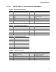
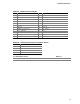
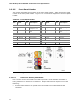
Table 18. S/PDIF Connector
Pin Signal Name
1 VCC
2 S/PDIF out
3 Ground
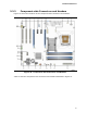
2.2.2.2 Add-in Card Connectors
The board has the following add-in card connectors:
• PCI Express 2.0 x16: two PCI Express 2.0 x16 connectors
⎯ Supports PCI Express GEN1 frequency of 1.25 GHz resulting in 2.5 Gb/s each
direction (500 MB/s total). Maximum theoretical bandwidth on interface of 4
GB/s in each direction simultaneously, for an aggregate of 8 GB/s when
operating in x16 mode.
⎯ Supports PCI Express GEN2 frequency of 2.5 GHz resulting in 5.0 Gb/s each
direction (1000 MB/s total). Maximum theoretical bandwidth on interface of 8
GB/s in each direction simultaneously, for an aggregate of 16 GB/s when
operating in x16 mode.
NOTE
If both PCI Express x16 slots are populated, the effective bandwidth will be at x8 for
each slot. Both cards must be PCI Express 2.0 compatible to achieve PCI Express 2.0
bandwidth.
• PCI Express x1: two PCI Express x1 connectors.
⎯ The x1 interface supports simultaneous transfer speeds up to 250 Mbytes/sec
of peak bandwidth per direction and up to 500 MBytes/sec concurrent
bandwidth.
• PCI Conventional (rev 2.3 compliant) bus: three PCI Conventional bus add-in card
connectors.
⎯ The SMBus is routed to all PCI Conventional bus connectors. PCI Conventional
bus add-in cards with SMBus support can access sensor data and other
information residing on the board.
Note the following considerations for the PCI Conventional bus connectors:
• All of the PCI Conventional bus connectors are bus master capable.
• SMBus signals are routed to all PCI Conventional bus connectors. This enables PCI
Conventional bus add-in boards with SMBus support to access sensor data on the
board. The specific SMBus signals are as follows:
⎯ The SMBus clock line is connected to pin A40.
⎯ The SMBus data line is connected to pin A41.