Intel® Desktop Board DP43BF Product Guide Order Number: E88313-001
Revision History Revision -001 Revision History First release of the Intel® Desktop Board DP43BF Product Guide Date February 2010 Disclaimer INFORMATION IN THIS DOCUMENT IS PROVIDED IN CONNECTION WITH INTEL® PRODUCTS. NO LICENSE, EXPRESS OR IMPLIED, BY ESTOPPEL OR OTHERWISE, TO ANY INTELLECTUAL PROPERTY RIGHTS IS GRANTED BY THIS DOCUMENT.
Preface This Product Guide gives information about board layout, component installation, BIOS update, and regulatory compliance for Intel® Desktop Board DP43BF. Intended Audience The Product Guide is intended for technically qualified personnel. It is not intended for general audiences. Use Only for Intended Applications All Intel Desktop Boards are evaluated as Information Technology Equipment (I.T.E.
Intel Desktop Board DP43BF Product Guide Terminology The table below gives descriptions of some common terms used in the product guide.
Contents 1 Desktop Board Features Supported Operating Systems..............................................................................11 Desktop Board Components.................................................................................12 Online Support ..................................................................................................14 Processor..........................................................................................................14 Main Memory.................
Intel Desktop Board DP43BF Product Guide Installing the I/O Shield ......................................................................................29 Installing and Removing the Desktop Board ...........................................................30 Installing and Removing a Processor .....................................................................31 Installing a Processor ..................................................................................
Contents B Regulatory Compliance Safety Standards ...............................................................................................67 Place Battery Marking .................................................................................67 European Union Declaration of Conformity Statement..............................................68 Product Ecology Statements ................................................................................69 Recycling Considerations .......................
Intel Desktop Board DP43BF Product Guide Tables 1. 2. 3. 4. 5. 6. 7. 8. 9. 10. 11. 12. 13. 14. 15. 16. 17. 18. 19. 20. 21. viii Feature Summary.......................................................................................... 9 Intel Desktop Board DP43BF Components ........................................................13 Back Panel and Front Panel Audio Jack Retasking Support ..................................17 LAN Connector LEDs ................................................................
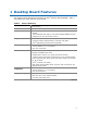
1 Desktop Board Features This chapter briefly describes the features of Intel® Desktop Board DP43BF. Table 1 summarizes the major features of the board. Table 1. Feature Summary Form Factor ATX (243.84 millimeters [9.60 inches] x 294.64 millimeters [11.
Intel Desktop Board DP43BF Product Guide Table 1. Feature Summary (continued) 10 Peripheral Interfaces • Twelve USB 2.0 ports provided by ICH10R: ― Six ports routed to the back panel ― Six ports routed to three front panel USB headers • Two IEEE 1394a ports provided by an onboard controller: one routed to an onboard header and one routed to a back panel connector • Five onboard Serial ATA (SATA) channels (3.
Desktop Board Features Supported Operating Systems The Desktop Board supports the following operating systems: • • • • • • • • • • • • • • • • • Microsoft Microsoft Microsoft Microsoft Microsoft Microsoft Microsoft Microsoft Microsoft Microsoft Microsoft Microsoft Microsoft Microsoft Microsoft Microsoft Microsoft Windows* 7 Ultimate Windows 7 Home Premium Windows 7 Basic Windows Vista* Ultimate Windows Vista Enterprise Windows Vista Business Windows Vista Home Premium Windows Vista Home Basic Windows Vis
Intel Desktop Board DP43BF Product Guide Desktop Board Components Figure 1 shows the approximate location of the major components on Intel Desktop Board DP43BF. Figure 1.
Desktop Board Features Table 2.
Intel Desktop Board DP43BF Product Guide Online Support For more information on Intel Desktop Board DP43BF consult the following online resources: • Intel Desktop Board DP43BF http://www.intel.com/products/motherboard/DP43BF/in dex.htm • Desktop Board support http://www.intel.com/support/motherboards/desktop/D P43BF • Available configurations for Intel Desktop Board DP43BF http://www.intel.com/products/motherboard/DP43BF/in dex.htm • Supported processors http://processormatch.intel.
Desktop Board Features Main Memory NOTE To be fully compliant with all applicable Intel ® SDRAM memory specifications, the board should be populated with DIMMs that support the Serial Presence Detect (SPD) data structure. If your memory modules do not support SPD, you will see a notification to this effect on the screen at power up. The BIOS will attempt to configure the memory controller for normal operation.
Intel Desktop Board DP43BF Product Guide Intel® P43 Express Chipset The Intel P43 Express Chipset consists of the following devices: • • Intel P43 Express Chipset Memory Controller Hub (MCH) with Direct Media Interface (DMI) Intel 82801JIR I/O Controller Hub (ICH10R) with DMI The MCH component provides interfaces to the processor, memory, PCI Express, and the DMI interconnect. ICH10R is a centralized controller for the board’s I/O paths.
Desktop Board Features Go to the following locations for more information about: • • • Audio drivers and utilities http://www.intel.com/support/motherboards/desktop Location of the onboard audio headers, Figure 22 on page 45 The location and description of the back panel audio connectors, Figure 23 on page 50 Table 3 lists the supported functions for the front panel and back panel audio jacks. Table 3.
Intel Desktop Board DP43BF Product Guide LAN Subsystem The LAN subsystem includes: • • • Intel ICH10R Broadcom NetLink BCM5788 Gigabit (10/100/1000 Mb/s) Ethernet LAN controller RJ-45 LAN connector with integrated status LEDs The subsystem features: • CSMA/CD protocol engine • LAN connect interface between ICH10R and the controller • PCI Express power management Two LEDs are built into the RJ-45 LAN connector located on the back panel (see Figure 2). These LEDs indicate the operating states of the LAN.
Desktop Board Features Hi-Speed USB 2.0 Support The Desktop Board supports up to 12 USB 2.0 ports (six ports routed to the back panel and six ports routed to three internal headers) via ICH10R. USB 2.0 ports are backward compatible with USB 1.1 devices. USB 1.1 devices will function normally at USB 1.1 speeds. USB 2.0 support requires both an operating system and drivers that fully support USB 2.0 transfer rates. Disabling Hi-Speed USB in the BIOS reverts all USB 2.0 ports to USB 1.1 operation.
Intel Desktop Board DP43BF Product Guide The PATA interface also supports ATAPI devices (such as CD-ROM drives) and ATA devices using the transfer modes. The BIOS supports Logical Block Addressing (LBA) and Extended Cylinder Head Sector (ECHS) translation modes. The drive reports the transfer rate and translation mode to the BIOS. SATA Interfaces The ICH10R SATA controller provides five SATA ports and one eSATA port with a theoretical maximum transfer rate of 3.0 Gb/s on each port.
Desktop Board Features Serial ATA RAID The five onboard Serial ATA channels support the following RAID (Redundant Array of Independent Drives) levels via Intel® Matrix Storage Technology: • • • • RAID RAID RAID RAID 0 - data striping 1 - data mirroring 0+1 (or RAID 10) - data striping and data mirroring 5 - distributed parity Expandability For system expansion, the Desktop Board provides the following expansion slots: • • • One PCI Express 2.0 x16 connector (compatible with PCI Express 1.
Intel Desktop Board DP43BF Product Guide Security Passwords The BIOS includes security features that restrict whether the BIOS Setup program can be accessed and who can boot the computer. A supervisor password and a user password can be set for the BIOS Setup and for booting the computer, with the following restrictions: • • • The supervisor password gives unrestricted access to view and change all Setup options.
Desktop Board Features Chassis Intrusion The board supports a chassis security feature that detects if the chassis cover has been removed. The security feature uses a mechanical switch on the chassis that can be connected to the chassis intrusion header on the Desktop Board. See Figure 22 for the location of the chassis intrusion header.
Intel Desktop Board DP43BF Product Guide Fan Headers The function/operation of the fans is as follows: • • • • • The fans are on when the computer is in the ACPI S0 state. The fans are off when the computer is in the ACPI S3, S4, or S5 state. All fan headers support closed-loop fan control that can adjust the fan speed according to thermal conditions. All fan headers have a +12 V DC connection. The system fan headers support auto-detection for 4-pin and 3-pin chassis fans.
Desktop Board Features The Desktop Board supports the PCI Bus Power Management Interface Specification. Add-in cards that support this specification can participate in power management and can be used to wake the computer. +5 V Standby Power Indicator CAUTION If the AC power has been switched off and the standby power indicator is still lit, disconnect the power cord before installing or removing any devices connected to the board. Failure to do so could damage the board and any attached devices.
Intel Desktop Board DP43BF Product Guide PME# Signal Wake-up Support When the PME# signal on the PCI bus is asserted, the computer wakes from an ACPI S1, S3, S4, or S5 state. WAKE# Signal Wake-up Support When the WAKE# signal on the PCI Express bus is asserted, the computer wakes from an ACPI S1, S3, S4, or S5 state. Wake from PS/2 Activity on the PS/2 ports wakes the computer from an ACPI S1 or S3 state. Speaker A piezoelectric speaker is mounted on the Desktop Board.
2 Installing and Replacing Desktop Board Components This chapter tells you how to: • • • • • • • • • • • • Install the I/O shield Install and remove the Desktop Board Install and remove a processor Install and remove memory Install and remove a PCI Express x16 card Connect the PATA (IDE) and SATA cables Connect to the internal headers Connect to the onboard audio system Connect chassis fan and power supply cables Set the BIOS configuration jumper Clear passwords Replace the battery Before You Begin CAUTIO
Intel Desktop Board DP43BF Product Guide Installation Precautions When you install and test the Desktop Board, observe all warnings and cautions in the installation instructions.
Installing and Replacing Desktop Board Components Installing the I/O Shield The Desktop Board comes with an I/O shield. When installed in the chassis, the shield blocks radio frequency transmissions, protects internal components from dust and foreign objects, and promotes correct airflow within the chassis. Install the I/O shield before installing the Desktop Board in the chassis. Place the shield inside the chassis as shown in Figure 4. Press the shield into place so that it fits tightly and securely.
Intel Desktop Board DP43BF Product Guide Installing and Removing the Desktop Board CAUTION Only qualified technical personnel should perform these procedures. Disconnect the computer from its power source before performing the procedures described here. Failure to disconnect the power before you open the computer can result in personal injury or equipment damage. Refer to your chassis manual for instructions on installing and removing the Desktop Board.
Installing and Replacing Desktop Board Components Installing and Removing a Processor This section contains information on how to install and remove a processor on the Desktop Board. Installing a Processor CAUTION Before installing or removing the processor, make sure the AC power has been removed by unplugging the power cord from the computer; the standby power LED should not be lit (see Figure 3 on page 25). Failure to do so could damage the processor and the board.
Intel Desktop Board DP43BF Product Guide 3. Lift the load plate (Figure 7, A). Do not touch the socket contacts (Figure 7, B). Figure 7. Lift the Load Plate 4. Remove the plastic protective socket cover from the load plate (Figure 8). Do not discard the protective socket cover. Always replace the socket cover if the processor is removed from the socket. Figure 8.
Installing and Replacing Desktop Board Components 5. Remove the processor from the protective processor cover. Hold the processor only at the edges, being careful not to touch the bottom of the processor (see Figure 9). Do not discard the protective processor cover. Always replace the processor cover if the processor is removed from the socket. Figure 9. Remove the Processor from the Protective Processor Cover 6. Hold the processor with your thumb and index fingers oriented as shown in Figure 10.
Intel Desktop Board DP43BF Product Guide 7. Pressing down on the load plate (Figure 11, A), close and engage the socket lever (Figure 11, B). Figure 11. Close the Load Plate Installing a Processor Fan Heat Sink Intel Desktop Board DP43BF has mounting holes for a processor fan heat sink. For instructions on how to attach the processor fan heat sink to the Desktop Board, refer to the boxed processor manual.
Installing and Replacing Desktop Board Components Connecting the Processor Fan Heat Sink Cable Connect the processor fan heat sink cable to the 4-pin processor fan header (see Figure 12). A fan with a 4-pin connector as shown in Figure 12, A is recommended; however, a fan with a 3-pin connector (Figure 12, B) can be used. However, since a fan with a 3-pin connector cannot use the onboard fan control, the fan will always operate at full speed. Figure 12.
Intel Desktop Board DP43BF Product Guide Installing and Removing Memory Intel Desktop board DP43BF has four 240-pin DDR3 DIMM sockets arranged as DIMM 0 and DIMM 1 in both Channel A and Channel B. Guidelines for Dual Channel Memory Configuration Before installing DIMMs, read and follow these guidelines for dual channel configuration. Two or Four DIMMs Install a matched pair of DIMMs equal in speed and size (see Figure 13) in DIMM 0 (blue) of channels A and B. Figure 13.
Installing and Replacing Desktop Board Components If additional memory is to be used, install another matched pair of DIMMs in DIMM 1 (black) in channels A and B (see Figure 14). Figure 14. Dual Channel Memory Configuration with Four DIMMs Three DIMMs If you want to use three DIMMs in a dual-channel configuration, install a matched pair of DIMMs equal in speed and size in the DIMM 0 (blue) socket of channel A and the DIMM 0 (blue) socket of channel B.
Intel Desktop Board DP43BF Product Guide Installing DIMMs To make sure you have the correct DIMM, place it on the illustration of the DDR3 DIMM in Figure 16. All the notches should match with the DDR3 DIMM. Figure 16.
Installing and Replacing Desktop Board Components To install a DIMM, follow these steps: 1. Observe the precautions in "Before You Begin" on page 27. 2. Turn off all peripheral devices connected to the computer. Turn off the computer and disconnect the AC power cord. 3. Remove the computer’s cover and locate the DIMM sockets (see Figure 17). Figure 17. Installing a DIMM 4. Make sure the clips at either end of the DIMM socket(s) are pushed outward to the open position. 5.
Intel Desktop Board DP43BF Product Guide Removing DIMMs To remove a DIMM, follow these steps: 1. 2. 3. 4. 5. Observe the precautions in "Before You Begin" on page 27. Turn off all peripheral devices connected to the computer. Turn off the computer. Remove the AC power cord from the computer. Remove the computer’s cover. Gently spread the retaining clips at each end of the DIMM socket. The DIMM pops out of the socket. 6.
Installing and Replacing Desktop Board Components Installing and Removing a PCI Express x16 Card CAUTION When installing a PCI Express x16 card on the Desktop Board, ensure that the card is fully seated in the PCI Express x16 connector before you power on the system. If the card is not fully seated in the PCI Express connector, an electrical short may result across the PCI Express connector pins.
Intel Desktop Board DP43BF Product Guide Removing the PCI Express x16 Card Follow these instructions to remove the PCI Express x16 card from the connector: 1. Observe the precautions in "Before You Begin" on page 27. 2. Remove the screw (Figure 19, A) that secures the card’s metal bracket to the chassis back panel. 3. Push the card ejector lever down using the tip of a pencil or similar tool (Figure 19, B) in the notch. This will release the card from the connector (C). 4. Pull the card straight up.
Installing and Replacing Desktop Board Components Connecting a PATA (IDE) Cable An IDE cable can be used to connect two IDE drives to the Desktop Board. The cable supports the ATA-66/100 transfer protocol. Figure 20 shows the correct installation of the cable. NOTES ATA-66/100 compatible cables are backward compatible with drives using slower transfer protocols.
Intel Desktop Board DP43BF Product Guide Connecting SATA Cables SATA cables support the Serial ATA (SATA) protocol. Each cable can be used to connect a single SATA drive to the Desktop Board. For correct cable function: 1. Observe the precautions in "Before You Begin" on page 27. 2. Attach one end the SATA cable to one of the SATA connectors on the board (Figure 21, A). 3. Attach the other end of the SATA cable to the SATA drive (Figure 21, B). Figure 21.
Installing and Replacing Desktop Board Components Connecting to Internal Headers Before connecting cables to the internal headers, observe the precautions in “Before You Begin” on page 27. Figure 22 shows the location of the internal headers. Figure 22.
Intel Desktop Board DP43BF Product Guide Front Panel HD Audio Header The front panel audio header shown in Figure 22, A supports both Intel HD Audio and AC ’97 Audio. Table 5 shows the pin assignments and signal names for HD Audio and Table 6 shows the pin assignments and signal names for AC ’97 Audio. Table 5.
Installing and Replacing Desktop Board Components IEEE 1394a Header See Figure 22, C for the location of the IEEE 1394a header. Table 8 shows the pin assignments for the header. Table 8. IEEE 1394a Header Signal Names Pin Signal Name Pin Signal Name 1 TPA1+ 2 TPA1- 3 Ground 4 Ground 5 TPA2+ 6 TPA2- 7 +12 V 8 +12 V 9 Key (no pin) 10 Ground Front Panel Header See Figure 22, D for the location of the front panel header. Table 9 shows the pin assignments for the front panel header.
Intel Desktop Board DP43BF Product Guide HD Audio Link Header See Figure 22, F for the location of the HD Audio Link header. Table 11 shows the pin assignments for the header. Table 11. HD Audio Link Header Signal Names Pin Signal Name Pin Signal Name 1 BCLK 2 Ground 3 RST# 4 3.3 Vcc 5 SYNC 6 Ground 7 SDO 8 3.3 Vcc 9 SDI0 10 +12 V 11 SDI1 12 Key 13 No Connection 14 3.3 V STBY 15 No Connection 16 Ground USB 2.0 Headers See Figure 22, G for the location of the three USB 2.
Installing and Replacing Desktop Board Components Chassis Intrusion Header Figure 22, H shows the location of the chassis intrusion header. This header can be connected to a mechanical switch on the chassis to detect if the chassis cover is removed. Table 13 shows the pin assignments for the chassis intrusion header. Table 13. Chassis Intrusion Header Signal Names Pin Signal Name 1 Ground 2 Intruder# Serial Port Header See Figure 22, I for the location of the serial port header.
Intel Desktop Board DP43BF Product Guide Connecting to the Audio System After installing the audio driver, the multi-channel audio feature can be enabled. Figure 23 shows the back panel audio connectors. Item Description A Rear surround B Center channel and LFE (subwoofer) C S/PDIF digital audio out (optical) D Line in/Side surround/Headphones E Mic In F Front speaker/Headphones Figure 23.
Installing and Replacing Desktop Board Components Connecting Chassis Fan and Power Supply Cables Chassis Fan Cables Connect chassis fan cables to the chassis fan headers on the Desktop Board. Figure 24 shows the location of the chassis fan headers. Figure 24.
Intel Desktop Board DP43BF Product Guide Power Supply Cables CAUTION Failure to use an appropriate power supply and/or not connecting the 12 V (2 x 2 pin) power connector to the Desktop Board may result in damage to the board or the system may not function properly. The 2 x 12 pin main power connector on the Desktop Board is backwards compatible with ATX12V power supplies with 2 x 10 connectors. Figure 25 shows the location of the Desktop Board power connectors. Figure 25.
Installing and Replacing Desktop Board Components Setting the BIOS Configuration Jumper NOTE Always turn off the power and unplug the power cord from the computer before moving the jumper. Moving the jumper with the power on may result in unreliable computer operation. Figure 26 shows the location of the Desktop Board’s BIOS configuration jumper block. Figure 26.
Intel Desktop Board DP43BF Product Guide Table 15. Jumper Settings for the BIOS Setup Program Modes Jumper Setting Mode Description Normal (default) (1-2) The BIOS uses the current configuration and passwords for booting. Configure (2-3) After the Power-On Self-Test (POST) runs, the BIOS displays the Maintenance Menu. Use this menu to clear passwords. Recovery (None) The BIOS recovers data in the event of a failed BIOS update.
Installing and Replacing Desktop Board Components 9. Press to save the current values and exit Setup. 10. Turn off the computer. Disconnect the computer’s power cord from the AC power source. 11. Remove the computer cover. 12. To restore normal operation, place the jumper on pins 1-2 as shown below. 13. Replace the cover, plug in the computer, and turn on the computer. Replacing the Battery A coin-cell battery (CR2032) powers the real-time clock and CMOS memory.
Intel Desktop Board DP43BF Product Guide VIKTIGT! Risk för explosion om batteriet ersätts med felaktig batterityp. Batterier ska kasseras enligt de lokala miljövårdsbestämmelserna. VARO Räjähdysvaara, jos pariston tyyppi on väärä. Paristot on kierrätettävä, jos se on mahdollista. Käytetyt paristot on hävitettävä paikallisten ympäristömääräysten mukaisesti. VORSICHT Bei falschem Einsetzen einer neuen Batterie besteht Explosionsgefahr.
Installing and Replacing Desktop Board Components UPOZORNÌNÍ V případě výměny baterie za nesprávný druh může dojít k výbuchu. Je-li to možné, baterie by měly být recyklovány. Baterie je třeba zlikvidovat v souladu s místními předpisy o životním prostředí. Προσοχή Υπάρχει κίνδυνος για έκρηξη σε περίπτωση που η μπαταρία αντικατασταθεί από μία λανθασμένου τύπου. Οι μπαταρίες θα πρέπει να ανακυκλώνονται όταν κάτι τέτοιο είναι δυνατό.
Intel Desktop Board DP43BF Product Guide UPOZORNENIE Ak batériu vymeníte za nesprávny typ, hrozí nebezpečenstvo jej výbuchu. Batérie by sa mali podľa možnosti vždy recyklovať. Likvidácia použitých batérií sa musí vykonávať v súlade s miestnymi predpismi na ochranu životného prostredia. POZOR Zamenjava baterije z baterijo drugačnega tipa lahko povzroči eksplozijo. Če je mogoče, baterije reciklirajte. Rabljene baterije zavrzite v skladu z lokalnimi okoljevarstvenimi predpisi. .
Installing and Replacing Desktop Board Components To replace the battery, follow these steps: 1. Observe the precautions in "Before You Begin" (see page 27). 2. Turn off all peripheral devices connected to the computer. Disconnect the computer’s power cord from the AC power source (wall outlet or power adapter). 3. Remove the computer cover. 4. Locate the battery on the board (see Figure 27). 5. Gently lift the battery retention clip away from the battery holder as shown in Figure 27.
Intel Desktop Board DP43BF Product Guide Figure 27.
3 Updating the BIOS The BIOS Setup program can be used to view and change the BIOS settings for the computer. You can access the BIOS Setup program by pressing the key after the Power-On Self-Test (POST) memory test begins and before the operating system boot begins. This chapter tells you how to update the BIOS by either using the Intel Express BIOS Update utility or the Intel® Flash Memory Update Utility, and how to recover the BIOS if an update fails.
Intel Desktop Board DP43BF Product Guide Updating the BIOS with the ISO Image BIOS Update File or the Intel® Flash Memory Update Utility You can use the information in this section to update the BIOS using either the Intel Flash Memory Update Utility or the ISO Image BIOS update file. Obtaining the BIOS Update File You can update to a new version of the BIOS by using the ISO Image BIOS update file (recommended), or Intel Flash Memory BIOS update file.
Updating the BIOS CAUTION Do not interrupt the process or the system may not function properly. Follow these instructions to upgrade the BIOS using the ISO Image BIOS file: 1. Download the ISO Image BIOS file. 2. Using software capable of uncompressing and writing an ISO image file to CD, burn the data to a blank CD. NOTE Copying the ISO Image BIOS file to CD will not work. The completed CD should contain multiple files and a directory. 3.
Intel Desktop Board DP43BF Product Guide CAUTION Do not interrupt the process or the system may not function properly. 1. Uncompress the BIOS update file and copy the .BIO file, IFLASH.EXE, and .ITK file (optional) to a bootable USB flash drive or other bootable USB media. 2. Configure the BIOS or use the F10 option during POST to boot to the USB device. 3. Manually run the IFLASH.EXE file from the USB device and manually update the BIOS.
A Error Messages and Indicators Intel Desktop Board DP43BF reports POST errors in two ways: • • By sounding a beep code and blinking the front panel power LED By displaying an error message on the monitor BIOS Beep Codes Whenever a recoverable error occurs during POST, the BIOS causes the board’s speaker to beep and the front panel power LED to blink an error message indicating the problem. Table 16 and Table 17 list the BIOS codes. Table 16.
Intel Desktop Board DP43BF Product Guide Table 17. Front-panel Power LED Blink Codes Type Pattern F2 Setup/F10 Boot Menu Prompt None Note BIOS update in progress Off when the update begins, then on for 0.5 second, then off for 0.5 second. The pattern repeats until the BIOS update is complete. Video error (no addin graphics card installed) On-off (0.5 second each) two times, then a 3.0-second pause (off), the entire pattern repeats (blink and pause) until the system is powered off.
B Regulatory Compliance This appendix contains the following regulatory compliance information for Intel Desktop Board DP43BF: • • • • • Safety standards European Union Declaration of Conformity statement Product Ecology statements Electromagnetic Compatibility (EMC) regulations Product certifications Safety Standards Intel Desktop Board DP43BF complies with the safety standards stated in Table 19 when correctly installed in a compatible host system. Table 19.
Intel Desktop Board DP43BF Product Guide European Union Declaration of Conformity Statement We, Intel Corporation, declare under our sole responsibility that the product Intel® Desktop Board DP43BF is in conformity with all applicable essential requirements necessary for CE marking, following the provisions of the European Council Directives 2004/108/EC (EMC Directive), 2006/95/EC (Low Voltage Directive), and 2002/95/EC (ROHS Directive).
Regulatory Compliance Polski Niniejszy produkt jest zgodny z postanowieniami Dyrektyw Unii Europejskiej 2004/108/EC, 206/95/EC i 2002/95/EC. Portuguese Este produto cumpre com as normas da Diretiva Européia 2004/108/EC, 2006/95/EC & 2002/95/EC. Español Este producto cumple con las normas del Directivo Europeo 2004/108/EC, 2006/95/EC & 2002/95/EC. Slovensky Tento produkt je v súlade s ustanoveniami európskych direktív 2004/108/EC, 2006/95/EC a 2002/95/EC.
Intel Desktop Board DP43BF Product Guide Deutsch Als Teil von Intels Engagement für den Umweltschutz hat das Unternehmen das Intel Produkt-Recyclingprogramm implementiert, das Einzelhandelskunden von Intel Markenprodukten ermöglicht, gebrauchte Produkte an ausgewählte Standorte für ordnungsgemäßes Recycling zurückzugeben. Details zu diesem Programm, einschließlich der darin eingeschlossenen Produkte, verfügbaren Standorte, Versandanweisungen, Bedingungen usw., finden Sie auf der http://intel.
Regulatory Compliance Portuguese Como parte deste compromisso com o respeito ao ambiente, a Intel implementou o Programa de Reciclagem de Produtos para que os consumidores finais possam enviar produtos Intel usados para locais selecionados, onde esses produtos são reciclados de maneira adequada. Consulte o site http://intel.
Intel Desktop Board DP43BF Product Guide China RoHS Intel Desktop Board DP43BF is a China RoHS-compliant product. The China Ministry of Information Industry (MII) stipulates that a material Self Declaration Table (SDT) must be included in a product’s user documentation. The SDT for Intel Desktop Board DP43BF is shown in Figure 28. Figure 28.
Regulatory Compliance EMC Regulations Intel Desktop Board DP43BF complies with the EMC regulations stated in Table 20 when correctly installed in a compatible host system. Table 20. EMC Regulations Regulation Title FCC 47 CFR Part 15, Subpart B Title 47 of the Code of Federal Regulations, Part 15, Subpart B, Radio Frequency Devices. (USA) ICES-003 Interference-Causing Equipment Standard, Digital Apparatus.
Intel Desktop Board DP43BF Product Guide radio or television reception, which can be determined by turning the equipment off and on, the user is encouraged to try to correct the interference by one or more of the following measures: • • • • Reorient or relocate the receiving antenna. Increase the separation between the equipment and the receiver. Connect the equipment to an outlet on a circuit other than the one to which the receiver is connected.
Regulatory Compliance Korea Class B Statement Korea Class B Statement translation: This equipment is for home use, and has acquired electromagnetic conformity registration, so it can be used not only in residential areas, but also other areas. Ensure Electromagnetic Compatibility (EMC) Compliance Before computer integration, make sure that the power supply and other modules or peripherals, as applicable, have passed Class B EMC testing and are marked accordingly.
Intel Desktop Board DP43BF Product Guide Product Certifications Board-Level Certification Markings Intel Desktop Board DP43BF has the product certification markings shown in Table 21. Table 21. Product Certification Markings Description Mark UL joint US/Canada Recognized Component mark. Includes adjacent UL file number for Intel Desktop Boards: E210882. FCC Declaration of Conformity logo mark for Class B equipment. CE mark.
Regulatory Compliance Chassis and Component Certifications Ensure that the chassis and certain components; such as the power supply, peripheral drives, wiring, and cables; are components certified for the country or market where used. Agency certification marks on the product are proof of certification. Typical product certifications include: In Europe The CE marking signifies compliance with all applicable European requirements.
Intel Desktop Board DP43BF Product Guide 78