Intel® Desktop Board DP35DP Product Guide Order Number: D87462-003
Revision History Revision -001 -002 -003 Revision History First release of the Intel® Desktop Board DP35DP Product Guide Second release of the Intel® Desktop Board DP35DP Product Guide Third release of the Intel® Desktop Board DP35DP Product Guide Date April 2007 May 2007 January 2008 If an FCC declaration of conformity marking is present on the board, the following statement applies: FCC Declaration of Conformity This device complies with Part 15 of the FCC Rules.
Preface This Product Guide gives information about board layout, component installation, BIOS update, and regulatory requirements for Intel® Desktop Board DP35DP. Intended Audience The Product Guide is intended for technically qualified personnel. It is not intended for general audiences. Use Only for Intended Applications All Intel Desktop Boards are evaluated as Information Technology Equipment (I.T.E.
Intel Desktop Board DP35DP Product Guide Conventions The following conventions are used in this manual: CAUTION Cautions warn the user about how to prevent damage to hardware or loss of data. NOTE Notes call attention to important information. Terminology The table below gives descriptions of some common terms used in the product guide.
Contents 1 Desktop Board Features Supported Operating Systems..............................................................................10 Desktop Board Components.................................................................................11 Processor..........................................................................................................13 Main Memory.....................................................................................................13 Intel® P35 Express Chipset ..
Intel Desktop Board DP35DP Product Guide Installing a Processor ..................................................................................29 Installing the Processor Fan Heat Sink ...........................................................32 Connecting the Processor Fan Heat Sink Cable................................................33 Removing the Processor ..............................................................................34 Installing and Removing Memory................................
Contents 5 Configuring for Intel® Rapid Recover Technology Enabling Intel Rapid Recover Technology...............................................................67 Creating a Recovery Volume ................................................................................68 Creating a Recovery Volume Using the RAID Option ROM .................................68 Creating a Recovery Volume Using the Intel Matrix Storage Console ..................68 Disk Synchronization Mode ...................................
Intel Desktop Board DP35DP Product Guide 26. Connecting Power Supply Cables ....................................................................53 27. Location of the BIOS Configuration Jumper Block ..............................................54 28. Removing the Battery ...................................................................................60 Tables 1. 2. 3. 4. 5. 6. 7. 8. 9. 10. 11. 12. 13. 14. 15. 16. 17. 18. 19. 20. viii Feature Summary...................................................
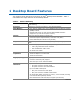
1 Desktop Board Features This chapter briefly describes the features of Intel® Desktop Board DP35DP. Table 1 summarizes the major features of the Desktop Board. Table 1. Feature Summary Form Factor ATX (320.04 millimeters [11.60 inches] x 243.84 millimeters [9.60 inches]) Processor Support for an Intel® processor in the LGA775 package Main Memory • Four 240-pin, DDR2 1.
Intel Desktop Board DP35DP Product Guide Table 1.
Desktop Board Features Desktop Board Components Figure 1 shows the approximate location of the major components on Desktop Board DP35DP. Figure 1.
Intel Desktop Board DP35DP Product Guide Table 2.
Desktop Board Features Related Links: Go to the following links for more information about: • Desktop Board DP35DP http://www.intel.com/design/motherbd http://support.intel.com/support/motherboards/desktop • • • Supported processors Audio software and utilities LAN software and drivers http://www.intel.com/go/findCPU http://www.intel.com/design/motherbd http://www.intel.
Intel Desktop Board DP35DP Product Guide • Support for: ⎯ Unbuffered, non-registered single or double-sided DIMMs ⎯ Non-ECC DDR2 memory ⎯ DIMM Type and Timings listed below: Type Timing DDR2-800 5-5-5 or 6-6-6 only DDR2-667 5-5-5 only ⎯ Serial Presence Detect (SPD) memory only ⎯ Memory configurations listed below: • Up to 2.0 GB utilizing 256 Mb technology • Up to 4.0 GB utilizing 512 Mb or 1 Gb technology • Up to 8.
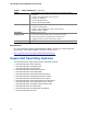
Desktop Board Features Audio Subsystem The onboard audio subsystem consists of the following: • • • • Intel® ICH9R I/O controller hub IDT STAC9271D audio codec Back panel audio connectors Onboard audio headers: ⎯ Intel High Definition audio front panel audio header ⎯ HD audio link header The audio subsystem supports the following features: • • • • Dolby* Home Theater support A signal-to-noise (S/N) ratio of 95 dB Independent multi-streaming 7.
Intel Desktop Board DP35DP Product Guide LAN Subsystem The LAN subsystem includes: • • • Intel ICH9R Intel 82566DC Gigabit (10/100/1000 Mb/s) Ethernet LAN controller RJ-45 LAN connector with integrated status LEDs The subsystem features: • CSMA/CD protocol engine • LAN connect interface between ICH9R and the LAN controller • PCI bus power management Related Links: Go to the following link for information about LAN software and drivers: http://support.intel.
Desktop Board Features Table 3 describes the LED states when the board is powered up and the LAN subsystem is operating. Table 3. LAN Connector LEDs LED LED Color LED State Indicates A Green Off LAN link is not established On LAN link is established B Blinking LAN activity is occurring N/A Off 10 Mb/s data rate Green On 100 Mb/s data rate Yellow On 1000 Mb/s data rate Hi-Speed USB 2.0 Support The Desktop Board supports up to 12 USB 2.
Intel Desktop Board DP35DP Product Guide Serial ATA The Desktop Board supports six Serial ATA channels (3.0 Gb/s) via ICH9R, connecting one device per channel. One channel is configured as an eSATA channel.
Desktop Board Features BIOS The BIOS provides the Power-On Self-Test (POST), the BIOS Setup program, the PCI/PCI Express and IDE auto-configuration utilities, and the video BIOS. The BIOS is stored in the Serial Peripheral Interface (SPI) Flash. The BIOS can be updated by following the instructions on page 61 in Chapter 3.
Intel Desktop Board DP35DP Product Guide Hardware Management Features The hardware management features of Desktop Board DP35DP enable the board to be compatible with the Wired for Management (WfM) specification.
Desktop Board Features Power Management Features Power management is implemented at several levels, including: • • • Software support through the Advanced Configuration and Power Interface (ACPI) Hardware support: ⎯ Power connectors ⎯ Fan headers ⎯ LAN wake capabilities ⎯ Instantly Available PC technology (Suspend to RAM) ⎯ +5 V standby power indicator LED ⎯ Wake from USB ⎯ Power Management Event signal (PME#) wakeup support ⎯ WAKE# signal wake-up support ENERGY STAR capable ACPI ACPI gives the operatin
Intel Desktop Board DP35DP Product Guide Fan Headers The function/operation of the fans is as follows: • • • • • The fans are on when the computer is in the ACPI S0 state. The fans are off when the computer is in the ACPI S3, S4, or S5 state. Each fan header is wired to a tachometer input of the hardware monitoring and control device. All fan headers support closed-loop fan control that can adjust the fan speed or switch the fan on or off as needed. All fan headers have a +12 V DC connection.
Desktop Board Features The Desktop Board supports the PCI Bus Power Management Interface Specification. Add-in cards that support this specification can participate in power management and can be used to wake the computer. +5 V Standby Power Indicator LED CAUTION If the AC power has been switched off and the standby power indicator is still lit, disconnect the power cord before installing or removing any devices connected to the board. Failure to do so could damage the board and any attached devices.
Intel Desktop Board DP35DP Product Guide PME# Signal Wake-up Support When the PME# signal on the PCI bus is asserted, the computer wakes from an ACPI S3, S4, or S5 state. WAKE# Signal Wake-up Support When the WAKE# signal on the PCI Express bus is asserted, the computer wakes from an ACPI S2, S3, S4, or S5 state. ENERGY STAR* Capable In 2007, the US Department of Energy and the US Environmental Protection Agency revised the ENERGY STAR requirements.
2 Installing and Replacing Desktop Board Components This chapter tells you how to: • • • • • • • • • • • • • Install the I/O shield Install and remove the Desktop Board Install and remove a processor Install and remove memory Install and remove a PCI Express x16 card Connect the IDE and Serial ATA cables Install the External SATA (eSATA) adapter bracket Connect to the internal headers Connect to the flexible audio system Connect chassis fan and power supply cables Set the BIOS configuration jumper Clear pa
Intel Desktop Board DP35DP Product Guide Installation Precautions When you install and test the Intel Desktop Board, observe all warnings and cautions in the installation instructions.
Installing and Replacing Desktop Board Components Installing the I/O Shield The Desktop Board comes with an I/O shield. When installed in the chassis, the shield blocks radio frequency transmissions, protects internal components from dust and foreign objects, and promotes correct airflow within the chassis. Install the I/O shield before installing the Desktop Board in the chassis. Place the shield inside the chassis as shown in Figure 4. Press the shield into place so that it fits tightly and securely.
Intel Desktop Board DP35DP Product Guide Installing and Removing the Desktop Board CAUTION Only qualified technical personnel should do this procedure. Disconnect the computer from its power source before performing the procedures described here. Failure to disconnect the power before you open the computer can result in personal injury or equipment damage. Refer to your chassis manual for instructions on installing and removing the Desktop Board.
Installing and Replacing Desktop Board Components Installing and Removing a Processor Instructions on how to install the processor to the Desktop Board are given below. Installing a Processor CAUTION Before installing or removing the processor, make sure the AC power has been removed by unplugging the power cord from the computer; the standby power LED should not be lit (see Figure 3 on page 23). Failure to do so could damage the processor and the board.
Intel Desktop Board DP35DP Product Guide 3. Lift the load plate (Figure 7, A). Do not touch the socket contacts (Figure 7, B). Figure 7. Lift the Load Plate 4. Remove the plastic protective socket cover from the load plate (Figure 8). Do not discard the protective socket cover. Always replace the socket cover if the processor is removed from the socket. Figure 8.
Installing and Replacing Desktop Board Components 5. Remove the processor from the protective processor cover. Hold the processor only at the edges, being careful not to touch the bottom of the processor (see Figure 9). Do not discard the protective processor cover. Always replace the processor cover if the processor is removed from the socket. Figure 9. Remove the Processor from the Protective Processor Cover 6. Hold the processor with your thumb and index fingers oriented as shown in Figure 10.
Intel Desktop Board DP35DP Product Guide 7. Pressing down on the load plate (Figure 11, A), close and engage the socket lever (Figure 11, B). Figure 11. Close the Load Plate Installing the Processor Fan Heat Sink Desktop Board DP35DP has mounting holes for a processor fan heat sink. For instructions on how to attach the processor fan heat sink to the Desktop Board, refer to the boxed processor manual.
Installing and Replacing Desktop Board Components Connecting the Processor Fan Heat Sink Cable Connect the processor fan heat sink cable to the 4-pin processor fan header (see Figure 12). A fan with a 4-pin connector as shown in Figure 12, A is recommended; however, a fan with a 3-pin connector (Figure 12, B) can be used. However, since the fan with a 3-pin connector cannot use the onboard fan control, the fan will always operate at full speed. Figure 12.
Intel Desktop Board DP35DP Product Guide Removing the Processor For instructions on how to remove the processor fan heat sink and processor, refer to the processor installation manual. Installing and Removing Memory NOTE To be fully compliant with all applicable Intel SDRAM memory specifications, the board requires DIMMs that support the Serial Presence Detect (SPD) data structure. Desktop board DP35DP has four 240-pin DDR2 DIMM sockets arranged as DIMM 0 and DIMM 1 in both Channel A and Channel B.
Installing and Replacing Desktop Board Components Guidelines for Dual Channel Memory Configuration Before installing DIMMs, read and follow these guidelines for dual channel configuration. Two or Four DIMMs Install a matched pair of DIMMs equal in speed and size (see Figure 13) in DIMM 0 (blue) of channels A and B. Figure 13. Dual Channel Memory Configuration with Two DIMMs If additional memory is to be used, install another matched pair of DIMMs in DIMM 1 (black) in channels A and B (see Figure 14).
Intel Desktop Board DP35DP Product Guide Three DIMMs If you want to use three DIMMs in a dual-channel configuration, install a matched pair of DIMMs equal in speed and size in DIMM 0 (blue) and DIMM 1 (black) of channel A. Install a DIMM equal in speed and total size of the DIMMs installed in channel A in either DIMM 0 or DIMM 1 of channel B (see Figure 15). Figure 15. Dual Channel Memory Configuration with Three DIMMs NOTE All other memory configurations will result in single channel memory operation.
Installing and Replacing Desktop Board Components Installing DIMMs To make sure you have the correct DIMM, place it on the illustration of the DDR2 DIMM in Figure 16. All the notches should match with the DDR2 DIMM. Figure 16.
Intel Desktop Board DP35DP Product Guide NOTE Memory must be installed in the Channel A, DIMM 0 socket to enable Intel Quiet System Technology. To install a DIMM, follow these steps: 1. Observe the precautions in "Before You Begin" on page 25. 2. Turn off all peripheral devices connected to the computer. Turn off the computer and disconnect the AC power cord. 3. Remove the computer’s cover and locate the DIMM sockets (see Figure 17). Figure 17. Installing a DIMM 4.
Installing and Replacing Desktop Board Components 7. Insert the bottom edge of the DIMM into the socket. 8. When the DIMM is inserted, push down on the top edge of the DIMM until the retaining clips snap into place. Make sure the clips are firmly in place. 9. Replace the computer’s cover and reconnect the AC power cord. Removing DIMMs To remove a DIMM, follow these steps: 1. 2. 3. 4. 5. Observe the precautions in "Before You Begin" on page 25. Turn off all peripheral devices connected to the computer.
Intel Desktop Board DP35DP Product Guide Installing and Removing a PCI Express x16 Card CAUTION When installing a PCI Express x16 card on the Desktop Board, ensure that the card is fully seated in the PCI Express x16 connector before you power on the system. If the card is not fully seated in the PCI Express connector, an electrical short may result across the PCI Express connector pins.
Installing and Replacing Desktop Board Components Removing the PCI Express x16 Card Follow these instructions to remove the PCI Express x16 card from the connector: 1. Observe the precautions in "Before You Begin" on page 25. 2. Remove the screw (Figure 19, A) that secures the card’s metal bracket to the chassis back panel. 3. Push the card ejector lever down using the tip of a pencil or similar tool (Figure 19, B) in the notch. This will release the card from the connector (C). 4.
Intel Desktop Board DP35DP Product Guide Connecting the IDE Cable The IDE cable can be used to connect two IDE drives to the Desktop Board. The cable supports the ATA-66/100 transfer protocol. Figure 20 shows the correct installation of the cable. NOTES ATA-66/100 compatible cables are backward compatible with drives using slower IDE transfer protocols.
Installing and Replacing Desktop Board Components Figure 20.
Intel Desktop Board DP35DP Product Guide Connecting the Serial ATA (SATA) Cables SATA cables support the Serial ATA protocol. Each cable can be used to connect a single internal SATA drive to the Desktop Board. For correct cable function: 1. Observe the precaution in “Before You Begin” on page 25. 2. Attach one end of the SATA cable to one of the black SATA connectors on the board (Figure 21, A) and attach the other end of the cable to the SATA drive (Figure 21, B).
Installing and Replacing Desktop Board Components Installing the External Serial ATA Adapter Bracket If you are connecting the external Serial ATA (eSATA) adapter bracket to the Desktop Board, follow these instructions (see Figure 22): 1. Observe the precautions in “Before You Begin” on page 25. 2. Attach the connector at the end of the adapter cable to the red SATA connector (Figure 22, B) on the Desktop Board. 3. Secure the bracket to the chassis back panel with a screw (Figure 22, A).
Intel Desktop Board DP35DP Product Guide Connecting to the Internal Headers Before connecting cables to the internal headers, observe the precautions in “Before You Begin” on page 25. Figure 23 shows the location of the internal headers. Item A Description HD Audio Link Item F Description Front Panel CIR Receiver (Input) B IEEE 1394a G Chassis Intrusion C Front panel audio H Alternate front panel power LED D Back Panel CIR Emitter (Output) I Front panel E Serial port J USB 2.
Installing and Replacing Desktop Board Components Connecting to the HD Audio Link Header See Figure 23, A for the location of the HD Audio Link header. Table 4 shows the pin assignments for the header. Table 4. HD Audio Link Header Signal Names Pin Signal Name Pin Signal Name 1 BCLK 2 Ground 3 RST# 4 3.3 Vcc 5 SYNC 6 Ground 7 SDO 8 3.3 Vcc 9 SDI0 10 +12 V 11 SDI1 12 Key 13 No Connection 14 3.
Intel Desktop Board DP35DP Product Guide To install the cable that connects the front panel audio solution to the front panel audio header, follow these steps: 1. Observe the precautions in "Before You Begin" on page 25. 2. Turn off all peripheral devices connected to the computer. Turn off the computer and disconnect the AC power cord. 3. Remove the cover. 4. Install a correctly keyed and shielded front panel audio cable.
Installing and Replacing Desktop Board Components Connecting to the Serial Port Header See Figure 23, E for the location of the serial port header. Table 9 shows the pin assignments for the header. Table 9. Serial Port Header Signal Names Pin Signal Name Pin Signal Name 1 DCD 2 RXD# 3 TXD# 4 DTR 5 Ground 6 DSR 7 RTS 8 CTS 9 RI 10 No Connection Connecting to the Chassis Intrusion Header Figure 23, G on page 46 shows the location of the chassis intrusion header.
Intel Desktop Board DP35DP Product Guide Connecting to the Front Panel Header Before connecting to the front panel header, observe the precautions in "Before You Begin" on page 25. See Figure 23, I on page 46 for the location of the multi-colored front panel header. Table 12 shows the pin assignments for the front panel header. Table 12.
Installing and Replacing Desktop Board Components Connecting to the Flexible Audio System After installing the SigmaTel* audio driver from the Intel Express Installer DVD-ROM, the multi-channel audio feature can be enabled. Figure 24 shows the back panel audio connectors. The default connector assignments are shown in the table.
Intel Desktop Board DP35DP Product Guide Connecting Chassis Fan and Power Supply Cables Connecting Chassis Fan Cables Connect chassis fan cables to the 3-pin and 4-pin chassis fan headers on the Desktop Board. Figure 25 shows the location of the chassis fan headers. Figure 25.
Installing and Replacing Desktop Board Components Connecting Supply Power Cables CAUTION Failure to use an appropriate power supply and/or not connecting the 12 V (2 x 2 pin) power connector to the Desktop Board may result in damage to the board or the system may not function properly. The 2 x 12 pin main power connector on the Desktop Board is backwards compatible with ATX12V power supplies with 2 x 10 connectors. Figure 26 shows the location of the Desktop Board power connectors. Figure 26.
Intel Desktop Board DP35DP Product Guide Setting the BIOS Configuration Jumper NOTE Always turn off the power and unplug the power cord from the computer before moving the jumper. Moving the jumper with the power on may result in unreliable computer operation. Figure 27 shows the location of the Desktop Board’s BIOS configuration jumper block. Figure 27. Location of the BIOS Configuration Jumper Block The three-pin BIOS jumper block enables all board configurations to be done in the BIOS Setup program.
Installing and Replacing Desktop Board Components Table 14. Jumper Settings for the BIOS Setup Program Modes Jumper Setting Mode Description Normal (default) (1-2) The BIOS uses the current configuration and passwords for booting. Configure (2-3) After the Power-On Self-Test (POST) runs, the BIOS displays the Maintenance Menu. Use this menu to clear passwords. Recovery (None) The BIOS recovers data in the event of a failed BIOS update.
Intel Desktop Board DP35DP Product Guide 11. Remove the computer cover. 12. To restore normal operation, place the jumper on pins 1-2 as shown below. 13. Replace the cover, plug in the computer, and turn on the computer. Replacing the Battery A coin-cell battery (CR2032) powers the real-time clock and CMOS memory. When the computer is not plugged into a wall socket, the battery has an estimated life of three years.
Installing and Replacing Desktop Board Components VIKTIGT! Risk för explosion om batteriet ersätts med felaktig batterityp. Batterier ska kasseras enligt de lokala miljövårdsbestämmelserna. VARO Räjähdysvaara, jos pariston tyyppi on väärä. Paristot on kierrätettävä, jos se on mahdollista. Käytetyt paristot on hävitettävä paikallisten ympäristömääräysten mukaisesti. VORSICHT Bei falschem Einsetzen einer neuen Batterie besteht Explosionsgefahr.
Intel Desktop Board DP35DP Product Guide UPOZORNÌNÍ V případě výměny baterie za nesprávný druh může dojít k výbuchu. Je-li to možné, baterie by měly být recyklovány. Baterie je třeba zlikvidovat v souladu s místními předpisy o životním prostředí. Προσοχή Υπάρχει κίνδυνος για έκρηξη σε περίπτωση που η μπαταρία αντικατασταθεί από μία λανθασμένου τύπου. Οι μπαταρίες θα πρέπει να ανακυκλώνονται όταν κάτι τέτοιο είναι δυνατό.
Installing and Replacing Desktop Board Components UPOZORNENIE Ak batériu vymeníte za nesprávny typ, hrozí nebezpečenstvo jej výbuchu. Batérie by sa mali podľa možnosti vždy recyklovať. Likvidácia použitých batérií sa musí vykonávať v súlade s miestnymi predpismi na ochranu životného prostredia. POZOR Zamenjava baterije z baterijo drugačnega tipa lahko povzroči eksplozijo. Če je mogoče, baterije reciklirajte. Rabljene baterije zavrzite v skladu z lokalnimi okoljevarstvenimi predpisi. .
Intel Desktop Board DP35DP Product Guide To replace the battery, follow these steps: 1. Observe the precautions in "Before You Begin" (see page 25). 2. Turn off all peripheral devices connected to the computer. Disconnect the computer’s power cord from the AC power source (wall outlet or power adapter). 3. Remove the computer cover. 4. Locate the battery on the board (see Figure 28). 5. With a medium flat-bladed screwdriver, gently pry the battery free from its connector.
3 Updating the BIOS The BIOS Setup program can be used to view and change the BIOS settings for the computer. You can access the BIOS Setup program by pressing the key after the Power-On Self-Test (POST) memory test begins and before the operating system boot begins. This chapter tells you how to update the BIOS by either using the Intel Express BIOS Update utility or the Iflash Memory Update utility, and how to recover the BIOS if an update fails.
Intel Desktop Board DP35DP Product Guide Updating the BIOS with the ISO Image BIOS Update File or the Iflash Memory Update Utility You can use the information in this section to update the BIOS using either the Iflash Memory Update Utility or the ISO Image BIOS update file. Obtaining the BIOS Update File You can update to a new version of the BIOS by using the ISO Image BIOS update file (recommended), or Iflash BIOS update file.
Updating the BIOS CAUTION Do not interrupt the process or the system may not function properly. Follow these instructions to upgrade the BIOS using the ISO Image BIOS file: 1. Download the ISO Image BIOS file. 2. Using software capable of uncompressing and writing an ISO image file to CD, burn the data to a blank CD. NOTE Copying the ISO Image BIOS file to CD will not work. The completed CD should contain multiple files and a directory. 3.
Intel Desktop Board DP35DP Product Guide CAUTION Do not interrupt the process or the system may not function properly. 1. Uncompress the BIOS update file and copy the .BIO file, IFLASH.EXE, and .ITK file (optional) to a bootable USB flash drive or other bootable USB media. 2. Configure the BIOS or use the F10 option during POST to boot to the USB device. 3. Manually run the IFLASH.EXE file from the USB device and manually update the BIOS.
4 Configuring for RAID (Intel® Matrix Storage Technology) NOTE Intel Matrix Storage Technology requires Microsoft Windows Vista or Microsoft Windows XP operating system and SATA hard drives. Configuring the BIOS for Intel Matrix Storage Technology 1. Assemble your system and attach one or more SATA hard drives to the SATA connectors. 2. Enter system BIOS Setup by pressing the key after the Power-On-Self-Test (POST) memory tests begin. 3.
Intel Desktop Board DP35DP Product Guide Loading the Intel Matrix Storage Technology RAID Drivers and Software 1. Begin Windows Setup by booting from the Windows installation CD. 2. If you will be using Microsoft Windows XP, press at the beginning of Windows Setup to install a third-party SCSI or RAID driver. When prompted, insert the diskette labeled Intel Matrix Storage Technology RAID Driver. Install the Intel® ICH9 SATA RAID Controller driver.
5 Configuring for Intel® Rapid Recover Technology Intel Rapid Recover technology utilizes RAID 1 (mirroring) functionality to copy data from a designated master drive to a designated recovery drive. The master and recovery drives must span 100 percent of the available hard drive space of an array, and only one recovery volume can be present on a system. You can select whether you want the master drive data to be copied to the recovery drive continuously or on request.
Intel Desktop Board DP35DP Product Guide Creating a Recovery Volume A recovery volume consists of two disks – a master disk and a recovery disk. A recovery volume can be created with either the RAID Option ROM (OROM) or the Intel® Matrix Storage Console application. Creating a Recovery Volume Using the RAID Option ROM To create a recovery volume using the RAID OROM, complete the following steps: 1. Enter the RAID OROM by pressing the and keys simultaneously when prompted during system POST. 2.
Configuring for Intel Rapid Recover Technology 6. Select the Update policy – Continuous update or Update on request. 7. Select Finish to complete the creation of the recovery volume. The system will synchronize the master disk with the recovery disk once after the creation of the recovery volume. Disk Synchronization Mode There are two modes of updating or synchronizing the recovery disk with the master disk – either continuous update or manual update.
Intel Desktop Board DP35DP Product Guide To un-mount the recovery disk, complete the following steps: 1. In the Advanced mode, right-click on the recovery volume name. 2. Select Access Recovery Drive Files. 3. Select OK on the information dialog box. The recovery disk is now un-mounted and reappears in Intel Matrix Storage Console.
A Error Messages and Indicators Desktop Board DP35DP reports POST errors in two ways: • • By sounding a beep code By displaying an error message on the monitor BIOS Beep Codes The BIOS also issues a beep code (one long tone followed by two short tones) during POST if the video configuration fails (a faulty video card or no card installed) or if an external ROM module does not properly checksum to zero. Table 15 lists the BIOS codes. Table 15.
Intel Desktop Board DP35DP Product Guide 72
B Regulatory Compliance This appendix contains the following regulatory compliance information for Desktop Board DP35DP: • • • • • Safety regulations European Union Declaration of Conformity statement Product Ecology statements Electromagnetic Compatibility (EMC) regulations Product certifications Safety Regulations Desktop Board DP35DP complies with the safety regulations stated in Table 17 when correctly installed in a compatible host system. Table 17.
Intel Desktop Board DP35DP Product Guide European Union Declaration of Conformity Statement We, Intel Corporation, declare under our sole responsibility that the product Intel® Desktop Board DP35DP is in conformity with all applicable essential requirements necessary for CE marking, following the provisions of the European Council Directive 89/336/EEC (EMC Directive) and Council Directive 73/23/EEC (Safety/Low Voltage Directive).
Regulatory Compliance Lietuvių Šis produktas atitinka Europos direktyvų 89/336/EEC ir 73/23/EEC nuostatas. Malti Dan il-prodott hu konformi mal-provvedimenti tad-Direttivi Ewropej 89/336/EEC u 73/23/EEC. Norsk Dette produktet er i henhold til bestemmelsene i det europeiske direktivet 89/336/ EEC & 73/23/EEC. Polski Niniejszy produkt jest zgodny z postanowieniami Dyrektyw Unii Europejskiej 89/336/EWG i 73/23/EWG. Portuguese Este produto cumpre com as normas da Diretiva Européia 89/336/EEC & 73/23/EEC.
Intel Desktop Board DP35DP Product Guide Product Ecology Statements The following information is provided to address worldwide product ecology concerns and regulations. Recycling Considerations As part of its commitment to environmental responsibility, Intel has implemented the Intel® Product Recycling Program to allow retail consumers of Intel’s branded products to return used products to select locations for proper recycling. Please consult http://www.intel.
Regulatory Compliance Français Dans le cadre de son engagement pour la protection de l'environnement, Intel a mis en œuvre le programme Intel Product Recycling Program (Programme de recyclage des produits Intel) pour permettre aux consommateurs de produits Intel de recycler les produits usés en les retournant à des adresses spécifiées. Visitez la page Web http://www.intel.
Intel Desktop Board DP35DP Product Guide Türkçe Intel, çevre sorumluluğuna bağımlılığının bir parçası olarak, perakende tüketicilerin Intel markalı kullanılmış ürünlerini belirlenmiş merkezlere iade edip uygun şekilde geri dönüştürmesini amaçlayan Intel Ürünleri Geri Dönüşüm Programı’nı uygulamaya koymuştur. Bu programın ürün kapsamı, ürün iade merkezleri, nakliye talimatları, kayıtlar ve şartlar v.s dahil bütün ayrıntılarını ögrenmek için lütfen http://www.intel.
Regulatory Compliance Table 18. Lead-Free Board Markings Description Mark nd Lead-Free 2 Level Interconnect: This symbol is used to identify electrical and electronic assemblies and components in which the lead (Pb) concentration level in the Intel Desktop Board substrate and the solder connections from the board to the components (second-level interconnect) is not greater than 0.1% by weight (1000 ppm).
Intel Desktop Board DP35DP Product Guide EMC Regulations Desktop Board DP35DP complies with the EMC regulations stated in Table 19 when correctly installed in a compatible host system. Table 19. EMC Regulations 80 Regulation Title FCC Class B Title 47 of the Code of Federal Regulations, Parts 2 and 15, Subpart B, Radio Frequency Devices. (USA) ICES-003 (Class B) Interference-Causing Equipment Standard, Digital Apparatus.
Regulatory Compliance Japanese Kanji statement translation: This is a Class B product based on the standard of the Voluntary Control Council for Interference from Information Technology Equipment (VCCI). If this is used near a radio or television receiver in a domestic environment, it may cause radio interference. Install and use the equipment according to the instruction manual. Korean Class B statement translation: This is household equipment that is certified to comply with EMC requirements.
Intel Desktop Board DP35DP Product Guide Product Certifications Board-Level Certification Markings Desktop Board DP35DP has the following product certification markings: Table 20. Product Certification Markings Description Mark UL joint US/Canada Recognized Component mark. Includes adjacent UL file number for Intel Desktop Boards: E210882. FCC Declaration of Conformity logo mark for Class B equipment. Includes Intel name and DP35DP model designation. CE mark.
Regulatory Compliance Chassis and Component Certifications Ensure that the chassis and certain components; such as the power supply, peripheral drives, wiring, and cables; are components certified for the country or market where used. Agency certification marks on the product are proof of certification. Typical product certifications include: In Europe The CE marking signifies compliance with all applicable European requirements.
Intel Desktop Board DP35DP Product Guide 84