Intel® Desktop Board DH77DF Technical Product Specification July 2013 Part Number: G54939-004 The Intel Desktop Board DH77DF may contain design defects or errors known as errata that may cause the product to deviate from published specifications. Current characterized errata are documented in the Intel Desktop Board DH77DF Specification Update.
Revision History Revision Revision History Date ® -001 First release of the Intel Desktop Board DH77DF Technical Product Specification April 2012 -002 Specification Clarification October 2012 -003 Specification Clarification May 2013 -004 Specification Clarification July 2013 This product specification applies to only the standard Intel® Desktop Board with BIOS identifier KCH7710H.86A. INFORMATION IN THIS DOCUMENT IS PROVIDED IN CONNECTION WITH INTEL® PRODUCTS.
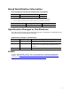
Board Identification Information Basic Desktop Board DH77DF Identification Information AA Revision BIOS Revision Notes G40293 KCH7710H.86A.0069 1,2 Notes: 1. The AA number is found on a small label on the component side of the board. 2.
Intel Desktop Board DH77DF Technical Product Specification iv
Preface This Technical Product Specification (TPS) specifies the board layout, components, connectors, power and environmental requirements, and the BIOS for Intel® Desktop Board DH77DF. Intended Audience The TPS is intended to provide detailed, technical information about Intel Desktop Board DH77DF and its components to the vendors, system integrators, and other engineers and technicians who need this level of information. It is specifically not intended for general audiences.
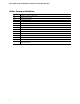
Intel Desktop Board DH77DF Technical Product Specification Other Common Notation vi # Used after a signal name to identify an active-low signal (such as USBP0#) GB Gigabyte (1,073,741,824 bytes) GB/s Gigabytes per second Gb/s Gigabits per second KB Kilobyte (1024 bytes) Kb Kilobit (1024 bits) kb/s 1000 bits per second MB Megabyte (1,048,576 bytes) MB/s Megabytes per second Mb Megabit (1,048,576 bits) Mb/s Megabits per second TDP Thermal Design Power xxh An address or data value e
Contents Revision History Board Identification Information ..................................................................iii Specification Changes or Clarifications .........................................................iii Errata ......................................................................................................iii Preface Intended Audience..................................................................................... v What This Document Contains............................
Intel Desktop Board DH77DF Technical Product Specification 1.11 Power Management .......................................................................... 38 1.11.1 ACPI .................................................................................... 38 1.11.2 Hardware Support ................................................................. 40 2 Technical Reference 2.1 Memory Resources ........................................................................... 45 2.1.1 Addressable Memory............
Contents 4 Error Messages and Beep Codes 4.1 4.2 4.3 4.4 4.5 Speaker .......................................................................................... 81 BIOS Beep Codes ............................................................................. 81 Front-panel Power LED Blink Codes ..................................................... 82 BIOS Error Messages ........................................................................ 82 Port 80h POST Codes ...........................................
Intel Desktop Board DH77DF Technical Product Specification 6. 7. 8. 9. 10. 11. 12. 13. 14. 15. 16. 17. 18. 19. 20. 21. 22. 23. 24. 25. 26. 27. 28. 29. 30. 31. 32. 33. 34. 35. 36. 37. 38. 39. 40. 41. 42. 43. 44. 45. 46. 51. 47. 48. 49. 50. 51. x HDMI Port Status Conditions .............................................................. 26 DisplayPort Status Conditions............................................................. 27 Audio Formats Supported by the HDMI and DisplayPort Interfaces ..........
Contents 52. 53. 54. 55. 56. Port 80h POST Codes ........................................................................ 84 Typical Port 80h POST Sequence ........................................................ 88 Safety Standards .............................................................................. 89 EMC Regulations ............................................................................... 95 Regulatory Compliance Marks ............................................................
Intel Desktop Board DH77DF Technical Product Specification xii
1 Product Description 1.1 Overview 1.1.1 Feature Summary Table 1 summarizes the major features of the board. Table 1. Feature Summary Form Factor Mini ITX (6.7 inches by 6.7 inches [170.18 millimeters by 170.
Intel Desktop Board DH77DF Technical Product Specification Table 1. Feature Summary (continued) Peripheral Interfaces • Four USB 3.0 ports: ― Two USB 3.0 ports are implemented with stacked back panel connectors (blue) ― Two front panel USB 3.0 ports are implemented through one internal connector (blue) • Ten USB 2.
Product Description 1.1.2 Board Layout (Top) Figure 1 shows the location of the major components on the top-side of the Intel Desktop Board DH77DF. Figure 1.
Intel Desktop Board DH77DF Technical Product Specification Table 2 lists the components identified in Figure 1. Table 2. Components Shown in Figure 1 16 Item/callout from Figure 1 Description A Back panel connectors B Battery C Intel H77 Express Chipset D BIOS configuration jumper block E IEEE 1394a front panel header (blue) F SATA 3.0 Gb/s connectors (black) G SATA 6.0 Gb/s connectors (blue) H Front panel header I Front panel USB 2.0 header J Front panel USB 3.
Product Description 1.1.3 Board Layout (Bottom) Figure 2 shows the location of the major components on the bottom-side of the board. Figure 2. Major Board Components (Bottom) Table 3.
Intel Desktop Board DH77DF Technical Product Specification 1.1.4 Block Diagram Figure 3 is a block diagram of the major functional areas of the board. Figure 3.
Product Description 1.2 1.3 Online Support To find information about… Visit this World Wide Web site: Intel Desktop Board DH77DF http://www.intel.com/products/motherboard/index.htm Desktop Board Support http://www.intel.com/p/en_US/support?iid=hdr+support Available configurations for Intel Desktop Board DH77DF http://ark.intel.com Supported processors http://processormatch.intel.com Chipset information http://www.intel.com/products/desktop/chipsets/index.
Intel Desktop Board DH77DF Technical Product Specification 1.3.1 Graphics Subsystem The board supports graphics through either the processor Intel HD Graphics or a PCI Express x16 add-in graphics card. 1.3.1.1 Processor Graphics The board supports integrated graphics through the Intel® Flexible Display Interface (Intel® FDI) for processors with Intel HD Graphics.
Product Description 1.3.1.2 PCI Express x16 Graphics rd 3 generation Intel Core processor family processors support PCI Express 3.0, 2.x, and 1.x and 2nd generation Intel Core processor family processors support PCI Express 2.x and 1.x: • • • PCI Express 3.0 with a raw bit rate of 8.0 GT/s results in an effective bandwidth of 1 GB/s each direction per lane. The maximum theoretical bandwidth of the x16 interface is 16 GB/s in each direction, simultaneously, for a total bandwidth of 32 GB/s.
Intel Desktop Board DH77DF Technical Product Specification 1.4 System Memory The board has two DIMM sockets and supports the following memory features: • • • • 1.5 V DDR3 SDRAM DIMMs with gold plated contacts, with the option to raise the voltage to support higher performance DDR3 SDRAM DIMMs. 1.
Product Description 1.4.1 Memory Configurations rd The 3 generation Intel Core processor family and 2nd generation Intel Core processor family processors support the following types of memory organization: • • • Dual channel (Interleaved) mode. This mode offers the highest throughput for real world applications. Dual channel mode is enabled when the installed memory capacities of both DIMM channels are equal.
Intel Desktop Board DH77DF Technical Product Specification Figure 4 illustrates the memory channel and DIMM configuration. Figure 4.
Product Description Intel® H77 Express Chipset 1.5 Intel H77 Express Chipset with Intel Flexible Display Interconect (Intel FDI) and Direct Media Interface (DMI) interconnect provides interfaces to the processor and the display, USB, SATA, LPC, LAN, and PCI Express interfaces. The Intel H77 Express Chipset is a centralized controller for the board’s I/O paths. For information about Refer to The Intel H77 chipset http://www.intel.com/products/desktop/chipsets/index.
Intel Desktop Board DH77DF Technical Product Specification 1.5.2.3 Digital Visual Interface (DVI-I) The DVI-I port supports both digital and analog DVI displays. The maximum supported resolution is 1900 x 1200 (WUXGA). The DVI port is compliant with the DVI 1.0 specification. DVI analog output can also be converted to VGA using a DVIVGA converter. Depending on the type of add-in card installed in the PCI Express x16 connector, the DVI port will behave as described in Table 5. Table 5.
Product Description 1.5.2.5 DisplayPort* DisplayPort is a digital communication interface that utilizes differential signaling to achieve a high bandwidth bus interface designed to support connections between PCs and monitors, projectors, and TV displays. DisplayPort is suitable for display connections between consumer electronics devices such as high definition optical disc players, set top boxes, and TV displays. DisplayPort output can also be converted to HDMI using a DisplayPort-HDMI converter.
Intel Desktop Board DH77DF Technical Product Specification 1.5.3 USB The PCH contains up to two Enhanced Host Controller Interface (EHCI) host controllers that support USB high-speed signaling. High-speed USB 2.0 allows data transfers up to 480 Mb/s. All ports are high-speed, full-speed, and low-speed capable. The PCH also contains an integrated eXtensible Host Controller Interface (xHCI) host controller which supports USB 3.0 ports. This controller allows data transfers up to 5 Gb/s.
Product Description 1.5.4 SATA Interfaces The board provides six SATA connectors, through the PCH, which support one device each: • • • • Two SATA 6.0 Gb/s interfaces through the Intel H77 Express Chipset with Intel® Rapid Storage Technology RAID support (blue) Two internal Serial ATA (SATA) 3.
Intel Desktop Board DH77DF Technical Product Specification 1.5.4.1 SATA RAID The board supports Intel Rapid Storage Technology which provides the following RAID (Redundant Array of Independent Drives) levels via the Intel H77 Express Chipset: • • • • RAID RAID RAID RAID 1.5.4.
Product Description 1.6 Real-Time Clock Subsystem A coin-cell battery (CR2032) powers the real-time clock and CMOS memory. When the computer is not plugged into a wall socket, the battery has an estimated life of three years. When the computer is plugged in, the standby current from the power supply extends the life of the battery. The clock is accurate to ± 13 minutes/year at 25 ºC with 3.3 VSB applied via the power supply 5V STBY rail.
Intel Desktop Board DH77DF Technical Product Specification 1.8 Audio Subsystem The board supports Intel HD Audio via the Realtek ALC898 audio codec. The audio subsystem supports the following features: • • • • • • Advanced jack sense for the back panel audio jacks that enables the audio codec to recognize the device that is connected to an audio port. Digital-to-Analog Converters (DAC) with 110 dB SNR (A-weighting) and Analog-toDigital Converters (ADC) with 104 dB SNR (A-weighting).
Product Description 1.8.
Intel Desktop Board DH77DF Technical Product Specification 1.
Product Description 1.9.2 LAN Subsystem Software LAN software and drivers are available from Intel’s World Wide Web site. For information about Refer to Obtaining LAN software and drivers http://downloadcenter.intel.com 1.9.3 RJ-45 LAN Connector with Integrated LEDs Two LEDs are built into the RJ-45 LAN connector (shown in Figure 6). Item Description A Link LED (Green) B Data Rate LED (Green/Yellow) Figure 6.
Intel Desktop Board DH77DF Technical Product Specification 1.10 Hardware Management Subsystem The hardware management features enable the board to be compatible with the Wired for Management (WfM) specification. The board has several hardware management features, including the following: • • Thermal and voltage monitoring Chassis intrusion detection 1.10.
Product Description 1.10.4 Thermal Monitoring Figure 7 shows the locations of the thermal sensors and fan headers. Item Description A Thermal diode, located on the Intel H77 PCH B Thermal diode, located on the processor die C Processor fan header D System fan header Figure 7.
Intel Desktop Board DH77DF Technical Product Specification 1.11 Power Management Power management is implemented at several levels, including: • • Software support through Advanced Configuration and Power Interface (ACPI) Hardware support: Power connector Fan headers LAN wake capabilities Instantly Available PC technology Wake from USB PCI Express WAKE# signal support Wake from Consumer IR Wake from S5 +5 V Standby Power Indicator LED 1.11.
Product Description 1.11.1.1 System States and Power States Under ACPI, the operating system directs all system and device power state transitions. The operating system puts devices in and out of low-power states based on user preferences and knowledge of how devices are being used by applications. Devices that are not being used can be turned off. The operating system uses information from applications and user settings to put the system as a whole into a low-power state.
Intel Desktop Board DH77DF Technical Product Specification 1.11.1.2 Wake-up Devices and Events Table 13 lists the devices or specific events that can wake the computer from specific states. Table 13. Wake-up Devices and Events These devices/events can wake up the computer… …from this state Power switch S3, S4, S5 RTC alarm S3, S4, S5 (Note 1) LAN S3, S4, S5 (Note 1) USB S3 WAKE# S3, S4, S5 (Note 1) Consumer IR S3, S4, S5 (Note 2) (Note 1) Notes: 1.
Product Description NOTE The use of Wake from USB from an ACPI state requires an operating system that provides full ACPI support. 1.11.2.1 Power Connector ATX12V-compliant power supplies can turn off the system power through system control. When an ACPI-enabled system receives the correct command, the power supply removes all non-standby voltages. When resuming from an AC power failure, the computer returns to the power state it was in before power was interrupted (on or off).
Intel Desktop Board DH77DF Technical Product Specification 1.11.2.3 LAN Wake Capabilities CAUTION For LAN wake capabilities, the +5 V standby line for the power supply must be capable of providing adequate +5 V standby current. Failure to provide adequate standby current when implementing LAN wake capabilities can damage the power supply. LAN wake capabilities enable remote wake-up of the computer through a network.
Product Description 1.11.2.5 Wake from USB USB bus activity wakes the computer from an ACPI S3 state. NOTE Wake from USB requires the use of a USB peripheral that supports Wake from USB. 1.11.2.6 WAKE# Signal Wake-up Support When the WAKE# signal on the PCI Express bus is asserted, the computer wakes from an ACPI S3, S4, or S5 state. 1.11.2.7 Wake from Consumer IR CIR activity wakes the computer from an ACPI S3, S4, or S5 state. 1.11.2.
Intel Desktop Board DH77DF Technical Product Specification Figure 8.
2 Technical Reference 2.1 Memory Resources 2.1.1 Addressable Memory The board utilizes 16 GB of addressable system memory. Typically the address space that is allocated for add-in cards, PCI Express configuration space, BIOS (SPI Flash device), and chipset overhead resides above the top of DRAM (total system memory).
Intel Desktop Board DH77DF Technical Product Specification Figure 9.
Technical Reference 2.1.2 Memory Map Table 14 lists the system memory map. Table 14. System Memory Map Address Range (decimal) Address Range (hex) Size Description 1024 K - 16777216 K 100000 – 400000000 16382 MB Extended memory 960 K - 1024 K F0000 - FFFFF 64 KB Runtime BIOS 896 K - 960 K E0000 - EFFFF 64 KB Reserved 800 K - 896 K C8000 - DFFFF 96 KB Potential available high DOS memory (open to the PCI Conventional bus). Dependent on video adapter used.
Intel Desktop Board DH77DF Technical Product Specification 2.2.1 Back Panel Connectors Figure 10 shows the location of the back panel connectors for the board. Item Description A B C D E F G H I J K L M N O LAN port USB 3.0 ports USB 2.0 high current charging ports IEEE 1394a connector eSATA connector DVI-I connector HDMI connector USB 2.0 ports DisplayPort connector Rear surround Center channel and LFE (subwoofer) S/PDIF out (optical) Line in Line out/front speakers Mic-in/side surround Figure 10.
Technical Reference 2.2.2 Component-side Connectors and Headers (Top) Figure 11 shows the locations of the connectors and headers on the top-side of the board. Figure 11.
Intel Desktop Board DH77DF Technical Product Specification Table 15 lists the component-side connectors and headers identified in Figure 11. Table 15. Component-side Connectors and Headers Shown in Figure 11 50 Item/callout f rom Figure 11 Description A IEEE 1394a front panel header (blue) B SATA 3.0 Gb/s connectors (black) C SATA 6.0 Gb/s connectors (blue) D Front panel header E Front panel USB 2.0 header F Front panel USB 3.
Technical Reference 2.2.3 Component-side Connectors and Headers (Bottom) Figure 2 shows the location of the connectors and headers on the bottom-side of the board. Figure 12. Major Board Components (Bottom) Table 16.
Intel Desktop Board DH77DF Technical Product Specification 2.2.3.1 Signal Tables for the Connectors and Headers Table 17. Front Panel Audio Header for Intel HD Audio Pin Signal Name Pin Signal Name 1 [Port 1] Left channel 2 Ground 3 [Port 1] Right channel 4 PRESENCE# (Dongle present) 5 [Port 2] Right channel 6 [Port 1] SENSE_RETURN 7 SENSE_SEND (Jack detection) 8 Key (no pin) 9 [Port 2] Left channel 10 [Port 2] SENSE_RETURN Table 18.
Technical Reference Table 20. Front Panel USB 3.
Intel Desktop Board DH77DF Technical Product Specification Table 23. Chassis Intrusion Header Pin Signal Name 1 Intruder# 2 Ground Table 24. Processor and System (4-Pin) Fan Headers Pin Signal Name 1 Ground (Note) 2 +12 V 3 FAN_TACH 4 FAN_CONTROL Note: These fan headers use Pulse Width Modulation control for fan speed. Table 25.
Technical Reference Table 27. PCI Express Full-/Half-Mini Card Connector Pin Signal Name 1 WAKE# 2 +3.3 V aux 3 Reserved 4 GND 5 Reserved 6 1.5 V 7 CLKREQ# 8 Reserved 9 GND 10 Reserved 11 REFCLK- 12 Reserved 13 REFCLK+ 14 Reserved 15 GND 16 Reserved 17 Reserved 18 GND 19 Reserved 20 Reserved 21 GND 22 PERST# 23 PERn0 24 +3.3 V aux 25 PERp0 26 GND 27 GND 28 +1.
Intel Desktop Board DH77DF Technical Product Specification Table 27. PCI Express Full-/Half-Mini Card Connector (continued) Pin Signal Name Additional Signal Name 39 +3.3 V aux (mSATA) 3.3 V 40 GND 41 +3.3 V aux 42 LED_WWAN# 43 Reserved 44 LED_WLAN# 45 Reserved 46 LED_WPAN# 47 Reserved 48 +1.5V 49 Reserved 50 GND 51 Reserved 52 +3.3 V aux Table 28.
Technical Reference 2.2.3.2 Add-in Card Connectors The board has the following add-in card connectors: • • One PCI Express x16 (3.0/2.x/1.x) One PCI Express Full-/Half-Mini Card with support for mSATA NOTE PCI Express 3.0 is only supported by 3rd generation Intel Core processor family processors. 2.2.3.3 Power Supply Connectors The board has the following power supply connectors: • • Main power – a 2 x 12 connector.
Intel Desktop Board DH77DF Technical Product Specification 2.2.3.4 Front Panel Header This section describes the functions of the front panel header. Table 32 lists the signal names of the front panel header. Figure 13 is a connection diagram for the front panel header. Table 32.
Technical Reference 2.2.3.4.2 Reset Switch Header Pins 5 and 7 can be connected to a momentary single pole, single throw (SPST) type switch that is normally open. When the switch is closed, the board resets and runs the POST. 2.2.3.4.3 Power/Sleep LED Header Pins 2 and 4 can be connected to a one- or two-color LED. Table 33 shows the possible states for a one-color LED. Table 34 shows the possible states for a two-color LED. Table 33.
Intel Desktop Board DH77DF Technical Product Specification 2.2.3.6 Front Panel USB 2.0 Headers Figure 14 is a connection diagram for the front panel USB 2.0 headers. NOTE • • The +5 V DC power on the USB headers is fused. Use only a front panel USB connector that conforms to the USB 2.0 specification for high-speed USB devices. Figure 14. Connection Diagram for Front Panel USB 2.
Technical Reference 2.3 Jumper Block CAUTION Do not move the jumper with the power on. Always turn off the power and unplug the power cord from the computer before changing a jumper setting. Otherwise, the board could be damaged. Figure 15 shows the location of the jumper block. The 3-pin jumper block determines the BIOS Setup program’s mode. Table 36 describes the jumper settings for the three modes: normal, configure, and recovery.
Intel Desktop Board DH77DF Technical Product Specification Table 36. BIOS Setup Configuration Jumper Settings Function/Mode Jumper Setting Configuration Normal 1-2 The BIOS uses current configuration information and passwords for booting. Configure 2-3 After the POST runs, Setup runs automatically. The maintenance menu is displayed. Note that this Configure mode is the only way to clear the BIOS/CMOS settings.
Technical Reference 2.4 2.4.1 Mechanical Considerations Form Factor The board is designed to fit into an Mini-ITX form-factor chassis. Figure 16 illustrates the mechanical form factor for the board. Dimensions are given in inches [millimeters]. The outer dimensions are 6.7 inches by 6.7 inches [170.18 millimeters by 170.18 millimeters]. Location of the I/O connectors and mounting holes are in compliance with the ATX specification. Figure 16.
Intel Desktop Board DH77DF Technical Product Specification 2.5 Electrical Considerations 2.5.1 Power Supply Considerations CAUTION The +5 V standby line from the power supply must be capable of providing adequate +5 V standby current. Failure to do so can damage the power supply. The total amount of standby current required depends on the wake devices supported and manufacturing options. Additional power required will depend on configurations chosen by the integrator.
Technical Reference 2.5.2 Power Supervisor This board supports a version of the Power Supervisor feature which adds protection to the 5 VSB power rail by limiting potential electrical overstress events to a nondestructive level. 2.5.3 Fan Header Current Capability CAUTION The processor fan must be connected to the processor fan header, not to a chassis fan header. Connecting the processor fan to a chassis fan header may result in onboard component damage that will halt fan operation.
Intel Desktop Board DH77DF Technical Product Specification 2.6 Thermal Considerations CAUTION A chassis with a maximum internal ambient temperature of 38 oC at the processor fan inlet is a requirement. Use a processor heat sink that provides omni-directional airflow to maintain required airflow across the processor voltage regulator area.
Technical Reference Item Description A B C Intel H77 Express Chipset Processor voltage regulator area Processor Figure 17.
Intel Desktop Board DH77DF Technical Product Specification Table 40 provides maximum case temperatures for the components that are sensitive to thermal changes. The operating temperature, current load, or operating frequency could affect case temperatures. Maximum case temperatures are important when considering proper airflow to cool the board. Table 40.
Technical Reference 2.7 Reliability The Mean Time Between Failures (MTBF) prediction is calculated using component and subassembly random failure rates. The calculation is based on the Telcordia SR-332, Issue 2; Method I Case 3 50% electrical stress, 55 ºC ambient. The MTBF prediction is used to estimate repair rates and spare parts requirements. The MTBF data is calculated from predicted data at 55 ºC. The MTBF for the Intel Desktop Board DH77DF is 268,341 hours. 2.
Intel Desktop Board DH77DF Technical Product Specification 70
3 Overview of BIOS Features 3.1 Introduction The board uses an Intel BIOS that is stored in the Serial Peripheral Interface Flash Memory (SPI Flash) and can be updated using a disk-based program. The SPI Flash contains the BIOS Setup program, POST, the PCI auto-configuration utility, LAN EEPROM information, and Plug and Play support. The BIOS displays a message during POST identifying the type of BIOS and a revision code. The initial production BIOSs are identified as KCH7710H.86A.
Intel Desktop Board DH77DF Technical Product Specification Table 43 lists the BIOS Setup program menu features. Table 43.
Overview of BIOS Features 3.4 System Management BIOS (SMBIOS) SMBIOS is a Desktop Management Interface (DMI) compliant method for managing computers in a managed network. The main component of SMBIOS is the Management Information Format (MIF) database, which contains information about the computing system and its components. Using SMBIOS, a system administrator can obtain the system types, capabilities, operational status, and installation dates for system components.
Intel Desktop Board DH77DF Technical Product Specification To install an operating system that supports USB, verify that Legacy USB support in the BIOS Setup program is set to Enabled and follow the operating system’s installation instructions. 3.6 BIOS Updates The BIOS can be updated using either of the following utilities, which are available on the Intel World Wide Web site: • • • Intel® Express BIOS Update utility, which enables automated updating while in the Windows environment.
Overview of BIOS Features 3.6.2 Custom Splash Screen During POST, an Intel® splash screen is displayed by default. This splash screen can be augmented with a custom splash screen. The Intel Integrator’s Toolkit that is available from Intel can be used to create a custom splash screen. NOTE If you add a custom splash screen, it will share space with the Intel branded logo. For information about Refer to Intel Integrator Toolkit http://developer.intel.
Intel Desktop Board DH77DF Technical Product Specification 3.8 Boot Options In the BIOS Setup program, the user can choose to boot from a hard drive, optical drive, removable drive, or the network. The default setting is for the optical drive to be the first boot device, the hard drive second, removable drive third, and the network fourth. 3.8.1 Optical Drive Boot Booting from the optical drive is supported in compliance to the El Torito bootable CD-ROM format specification.
Overview of BIOS Features 3.9 Adjusting Boot Speed These factors affect system boot speed: • • • Selecting and configuring peripherals properly Optimized BIOS boot parameters Enabling the Fast Boot feature 3.9.1 Peripheral Selection and Configuration The following techniques help improve system boot speed: • • • • Choose a hard drive with parameters such as “power-up to data ready” in less than eight seconds that minimizes hard drive startup delays.
Intel Desktop Board DH77DF Technical Product Specification 3.10 Hard Disk Drive Password Security Feature The Hard Disk Drive Password Security feature blocks read and write accesses to the hard disk drive until the correct password is given. Hard Disk Drive Passwords are set in BIOS SETUP and are prompted for during BIOS POST. For convenient support of S3 resume, the system BIOS will automatically unlock drives on resume from S3.
Overview of BIOS Features NOTE Hard Disk Drive Password Security is not supported in PCH RAID mode. Secured hard disk drives attached to the system when the system is in PCH RAID mode will not be accessible due to the disabling of BIOS Hard Disk Drive Password support. 3.11 BIOS Security Features The BIOS includes security features that restrict access to the BIOS Setup program and who can boot the computer.
Intel Desktop Board DH77DF Technical Product Specification NOTE The BIOS complies with NIST Special Publication 800-147 BIOS Protection Guidelines / Recommendations of the National Institute of Standards and Technology. Refer to http://csrc.nist.gov/publications/nistpubs/800-147/NIST-SP800-147-April2011.pdf for more information. 3.
4 Error Messages and Beep Codes 4.1 Speaker The board-mounted speaker provides audible error code (beep code) information during POST. 4.2 For information about Refer to The location of the onboard speaker Figure 1, page 15 BIOS Beep Codes Whenever a recoverable error occurs during POST, the BIOS causes the board’s speaker to beep an error message describing the problem (see Table 49). Table 49. BIOS Beep Codes Type Pattern Frequency F2 Setup/F10 Boot Menu One 0.
Intel Desktop Board DH77DF Technical Product Specification 4.3 Front-panel Power LED Blink Codes Whenever a recoverable error occurs during POST, the BIOS causes the board’s front panel power LED to blink an error message describing the problem (see Table 50). Table 50. Front-panel Power LED Blink Codes Type Pattern Note F2 Setup/F10 Boot Menu None Prompt 4.4 BIOS update in progress Off when the update begins, then on for 0.5 seconds, then off for 0.5 seconds.
Error Messages and Beep Codes 4.5 Port 80h POST Codes During the POST, the BIOS generates diagnostic progress codes (POST codes) to I/O port 80h. If the POST fails, execution stops and the last POST code generated is left at port 80h. This code is useful for determining the point where an error occurred. Displaying the POST codes requires a POST card that can interface with the Low Pin Count (LPC) Debug connector.
Intel Desktop Board DH77DF Technical Product Specification Table 53.
Error Messages and Beep Codes Table 53.
Intel Desktop Board DH77DF Technical Product Specification Table 53.
Error Messages and Beep Codes Table 53. Port 80h POST Codes (continued) Port 80 Code Progress Code Enumeration Removable Media 0xB8 Resetting removable media 0xB9 Disabling removable media 0xBA Detecting presence of a removable media (IDE, CDROM detection etc.
Intel Desktop Board DH77DF Technical Product Specification Table 54.
5 Regulatory Compliance and Battery Disposal Information 5.1 Regulatory Compliance This section contains the following regulatory compliance information for Intel Desktop Board DH77DF: • • • • • 5.1.
Intel Desktop Board DH77DF Technical Product Specification 5.1.2 European Union Declaration of Conformity Statement We, Intel Corporation, declare under our sole responsibility that the product Intel® Desktop Board DH77DF is in conformity with all applicable essential requirements necessary for CE marking, following the provisions of the European Council Directive 2004/108/EC (EMC Directive), 2006/95/EC (Low Voltage Directive), and 2002/95/EC (ROHS Directive).
Regulatory Compliance and Battery Disposal Information Portuguese Este produto cumpre com as normas da Diretiva Européia 2004/108/EC, 2006/95/EC & 2002/95/EC. Español Este producto cumple con las normas del Directivo Europeo 2004/108/EC, 2006/95/EC & 2002/95/EC. Slovensky Tento produkt je v súlade s ustanoveniami európskych direktív 2004/108/EC, 2006/95/EC a 2002/95/EC. Slovenščina Izdelek je skladen z določbami evropskih direktiv 2004/108/EC, 2006/95/EC in 2002/95/EC.
Intel Desktop Board DH77DF Technical Product Specification Español Como parte de su compromiso de responsabilidad medioambiental, Intel ha implantado el programa de reciclaje de productos Intel, que permite que los consumidores al detalle de los productos Intel devuelvan los productos usados en los lugares seleccionados para su correspondiente reciclado. Consulte la http://www.intel.
Regulatory Compliance and Battery Disposal Information Russian В качестве части своих обязательств к окружающей среде, в Intel создана программа утилизации продукции Intel (Product Recycling Program) для предоставления конечным пользователям марок продукции Intel возможности возврата используемой продукции в специализированные пункты для должной утилизации. Пожалуйста, обратитесь на веб-сайт http://www.intel.
Intel Desktop Board DH77DF Technical Product Specification 5.1.4 China RoHS Intel Desktop Board DH77DF is a China RoHS-compliant product. The China Ministry of Information Industry (MII) stipulates that a material Self Declaration Table (SDT) must be included in a product’s user documentation. The SDT for Intel Desktop Board DH77DF is shown in Figure 18. Figure 18.
Regulatory Compliance and Battery Disposal Information 5.1.5 EMC Regulations Intel Desktop Board DH77DF complies with the EMC regulations stated in Table 56 when correctly installed in a compatible host system. Table 56. EMC Regulations Regulation Title FCC 47 CFR Part 15, Subpart B Title 47 of the Code of Federal Regulations, Part 15, Subpart B, Radio Frequency Devices. (USA) ICES-003 Interference-Causing Equipment Standard, Digital Apparatus.
Intel Desktop Board DH77DF Technical Product Specification • • Connect the equipment to an outlet on a circuit other than the one to which the receiver is connected. Consult the dealer or an experienced radio/TV technician for help. Any changes or modifications to the equipment not expressly approved by Intel Corporation could void the user’s authority to operate the equipment. Tested to comply with FCC standards for home or office use.
Regulatory Compliance and Battery Disposal Information 5.1.6 e-Standby and ErP Compliance Intel Desktop Board DH77DF meets the following program requirements in an adequate system configuration, including appropriate selection of an efficient power supply: • • • EPEAT* Korea e-Standby European Union Energy-related Products Directive 2013 (ErP) Lot 6 For information about Refer to Electronic Product Environmental Assessment Tool (EPEAT) http://www.epeat.net/ Korea e-Standby Program http://www.
Intel Desktop Board DH77DF Technical Product Specification 5.1.7 Regulatory Compliance Marks (Board Level) Intel Desktop Board DH77DF has the regulatory compliance marks shown in Table 57. Table 57. Regulatory Compliance Marks Description Mark UL joint US/Canada Recognized Component mark. Includes adjacent UL file number for Intel Desktop Boards: E210882. FCC Declaration of Conformity logo mark for Class B equipment. CE mark.
Regulatory Compliance and Battery Disposal Information 5.2 Battery Disposal Information CAUTION Risk of explosion if the battery is replaced with an incorrect type. Batteries should be recycled where possible. Disposal of used batteries must be in accordance with local environmental regulations. PRÉCAUTION Risque d'explosion si la pile usagée est remplacée par une pile de type incorrect. Les piles usagées doivent être recyclées dans la mesure du possible.
Intel Desktop Board DH77DF Technical Product Specification PRECAUCIÓN Existe peligro de explosión si la pila no se cambia de forma adecuada. Utilice solamente pilas iguales o del mismo tipo que las recomendadas por el fabricante del equipo. Para deshacerse de las pilas usadas, siga igualmente las instrucciones del fabricante. WAARSCHUWING Er bestaat ontploffingsgevaar als de batterij wordt vervangen door een onjuist type batterij. Batterijen moeten zoveel mogelijk worden gerecycled.
Regulatory Compliance and Battery Disposal Information AWAS Risiko letupan wujud jika bateri digantikan dengan jenis yang tidak betul. Bateri sepatutnya dikitar semula jika boleh. Pelupusan bateri terpakai mestilah mematuhi peraturan alam sekitar tempatan. OSTRZEŻENIE Istnieje niebezpieczeństwo wybuchu w przypadku zastosowania niewłaściwego typu baterii. Zużyte baterie należy w miarę możliwości utylizować zgodnie z odpowiednimi przepisami ochrony środowiska.
Intel Desktop Board DH77DF Technical Product Specification 小心 如果更換的電池類型不正確,可能會有爆炸的危險。請盡可能將電池送至回收處。請依照當地的環保 規範來處理使用過的電池。 주의 배터리를 잘못된 종류로 교체할 경우 폭발 위험이 있습니다. 가능한 경우 배터리는 재활용해야 하며, 수명이 다한 배터리를 폐기할 때는 각 지역의 환경법을 따라야 합니다. THẬN TRỌNG Có nguy cơ xảy ra nổ nếu thay pin không đúng loại. Pin cần được tái chế nếu có thể thực hiện được. Việc thải bỏ pin đã sử dụng phải tuân theo các quy định của địa phương về môi trường.
Regulatory Compliance and Battery Disposal Information 103