
Technical Product Specification
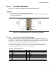

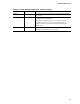


Table Of Contents
- Intel® Desktop Board DH61BE Technical Product Specification
- Revision History
- Preface
- Contents
- 1 Product Description
- 1.1 Overview
- 1.2 Legacy Considerations
- 1.3 Online Support
- 1.4 Processor
- 1.5 Intel® H61 Express Chipset
- 1.6 System Memory
- 1.7 Graphics Subsystem
- 1.8 USB
- 1.9 SATA Interfaces
- 1.10 Legacy I/O Controller
- 1.11 Audio Subsystem
- 1.12 LAN Subsystem
- 1.13 Real-Time Clock Subsystem
- 1.14 Thermal Monitoring
- 1.15 Platform Management and Security
- 1.16 Power Management
- 2 Technical Reference
- 3 Overview of BIOS Features
- 4 Error Messages and Beep Codes
- 5 Regulatory Compliance and Battery Disposal Information
Technical Reference
51
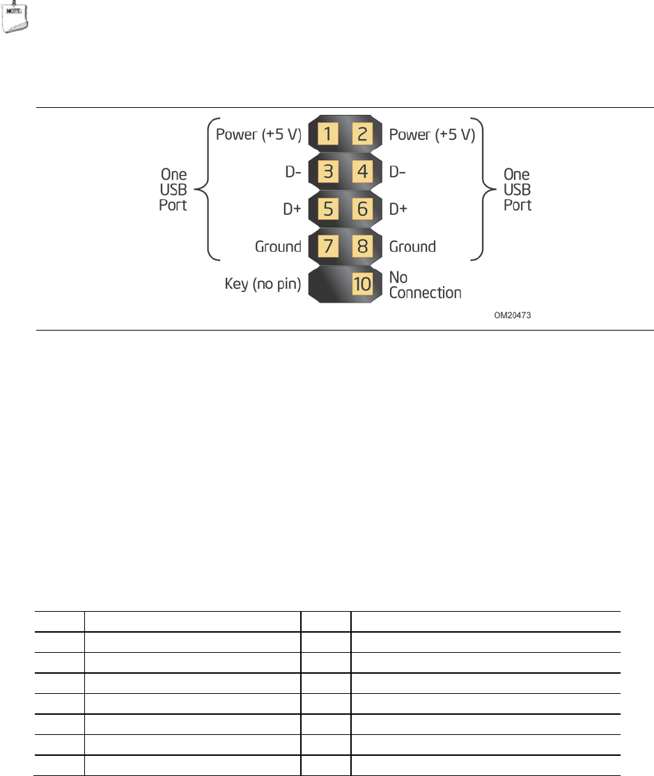
2.2.2.6 Front Panel USB Headers
Figure 12 is a connection diagram for the front panel USB headers.
NOTE
• The +5 V DC power on the USB headers is fused.
• Use only a front panel USB connector that conforms to the USB 2.0 specification for
high-speed USB devices.
Figure 12. Connection Diagram for Front Panel USB Headers
2.2.2.7 Low Pin Count (LPC) Debug Header
During the POST, the BIOS generates diagnostic progress codes (POST codes) to I/O
port 80h. If the POST fails, execution stops and the last POST code generated is left at
port 80h. This code is useful for determining the point where an error occurred (refer
to Section 4.5 on page 69 for a description of the POST codes).
Displaying the POST codes requires a POST card that can interface with the Low Pin
Count (LPC) Debug header. The POST card can decode the port and display the
contents on a medium such as a seven-segment display.
Table 26. LPC Debug Header
Pin
Signal Name
Pin
Signal Name
1 CK_33M_DEBUG 2 GND
3 PLTRST# 4 LFRAME#
5 LAD0 6 LAD1
7 LAD2 8 LAD3
9 GND 10 GND
11 +3.3 V 12 +3.3 V
13 Not connected 14 +3.3 V