
Technical Product Specification


Technical Reference
55
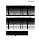
Table 24. SATA Power Connector
Pin Signal Name
1 3.3 V DC
2 3.3 V DC
3 3.3 V DC
4 Ground
5 Ground
6 Ground
7 5 V DC
8 5 V DC
9 5 V DC
10 Ground
11 Ground
12 Ground
13 12 V DC
14 12 V DC
15 12 V DC
Table 25. Fan Headers
Pin 4-Wire Support Pin 3-Wire Support
1 Ground 1 Ground
2 +12 V 2 FAN_POWER
3 FAN_TACH 3 FAN_TACH
4 FAN_CONTROL N/A N/A
Note: Fan speed control on this header uses Pulse Width Modulation for 4-wire fans and linear-voltage
for 3-wire fans.
Table 26. Front Panel CIR Receiver (Input) Header
Pin
Signal Name
1 Ground
2 LED
3 NC
4 Learn-in
5 5 V standby
6 VCC
7 Key (no pin)
8 CIR input