
Product guide
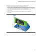
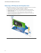
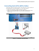
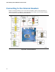


Table Of Contents
- Intel® Desktop Board DH57JG Product Guide
- Revision History
- Preface
- Contents
- 1 Desktop Board Features
- 2 Installing and Replacing Desktop Board Components
- Before You Begin
- Installation Precautions
- Installing the I/O Shield
- Installing and Removing the Desktop Board
- Installing and Removing a Processor
- Installing and Removing System Memory
- Installing and Removing PCI Express x16 Graphics Cards
- Connecting Serial ATA (SATA) Cables
- Connecting to the Internal Headers
- Connecting to the Audio System
- Connecting Chassis Fan and Power Supply Cables
- Setting the BIOS Configuration Jumper
- Clearing Passwords
- Replacing the Battery
- 3 Updating the BIOS
- A Error Messages and Indicators
- B Regulatory Compliance
Intel Desktop Board DH57JG Product Guide
50
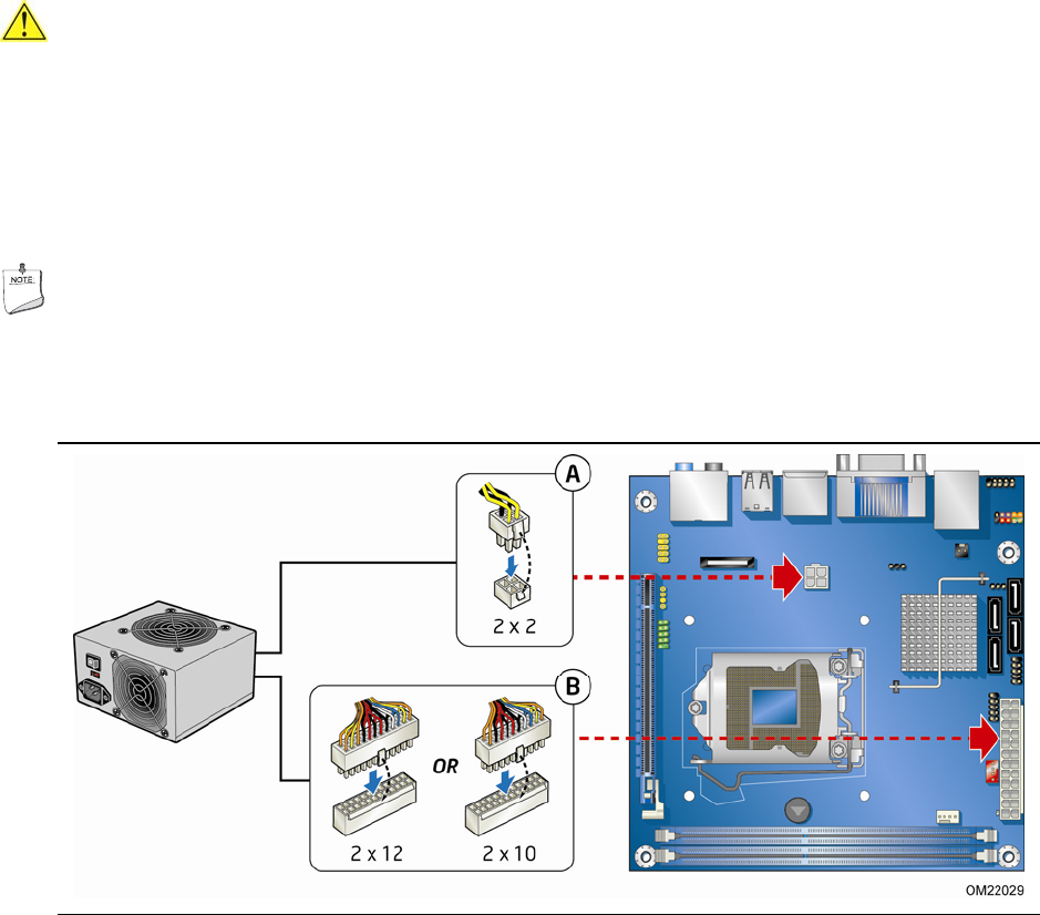
Connecting Power Supply Cables
CAUTION
Failure to use an appropriate power supply and/or not connecting the 12 V power
connector (Figure 23, A) to the Desktop Board may result in da
mage to the board or
the system may not function properly.
Figure 23 shows the location of the power connectors.
The 2 x 12 pin main power
connector (Figure 23, B) is backwards compatible with ATX12V power supplies with
2 x 10
connectors.
NOTE
If your power supply has a 2 x 10 main power connector, it is recommended that you
do not install a PCI Express x16 graphics card unless it has a direct connection to the
power supply.
Figure 23. Connecting Power Supply Cables
1. Observe the precautions in "Before You Begin" on page 27.
2. Connect the 12 V processor core voltage power supply cable to the 2 x 2 pin
connector (Figure 23, A).
3. Con
nect the main power supply cable to the 2 x 12 pin connector (Figure 23, B).