
Product guide
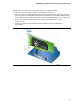
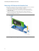
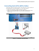
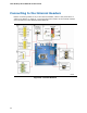


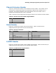


Table Of Contents
- Intel® Desktop Board DH57JG Product Guide
- Revision History
- Preface
- Contents
- 1 Desktop Board Features
- 2 Installing and Replacing Desktop Board Components
- Before You Begin
- Installation Precautions
- Installing the I/O Shield
- Installing and Removing the Desktop Board
- Installing and Removing a Processor
- Installing and Removing System Memory
- Installing and Removing PCI Express x16 Graphics Cards
- Connecting Serial ATA (SATA) Cables
- Connecting to the Internal Headers
- Connecting to the Audio System
- Connecting Chassis Fan and Power Supply Cables
- Setting the BIOS Configuration Jumper
- Clearing Passwords
- Replacing the Battery
- 3 Updating the BIOS
- A Error Messages and Indicators
- B Regulatory Compliance
Installing and Replacing Desktop Board Components
47
Chassis Intrusion Header
Figure 20, E shows the location of the chassis intrusion header. This header can be
connected to a mechanical switch on the chassis to detect if the chassis cover is
removed. This switch should be in the open position when the chassis cover is
installed and closed when the cover is removed.
Table 12 shows the pin assignments and
signal names for the chassis intrusion header.
Table 12. Chassis Intrusion Header Signal Names
Pin Description
1 Intruder#
2 Ground
Serial Header
Figure 20, F shows the location of the serial header. Table 13 shows the pin
assignments and signal names for the serial header.
Table 13. Serial Port Header
Pin Signal Name Pin Signal Name
1 DCD (Data Carrier Detect) 2 RXD# (Receive Data)
3 TXD# (Transmit Data) 4 DTR (Data Terminal Ready)
5 Ground 6 DSR (Data Set Ready)
7 RTS (Request To Send) 8 CTS (Clear To Send)
9 RI (Ring Indicator) 10 Key (no pin)
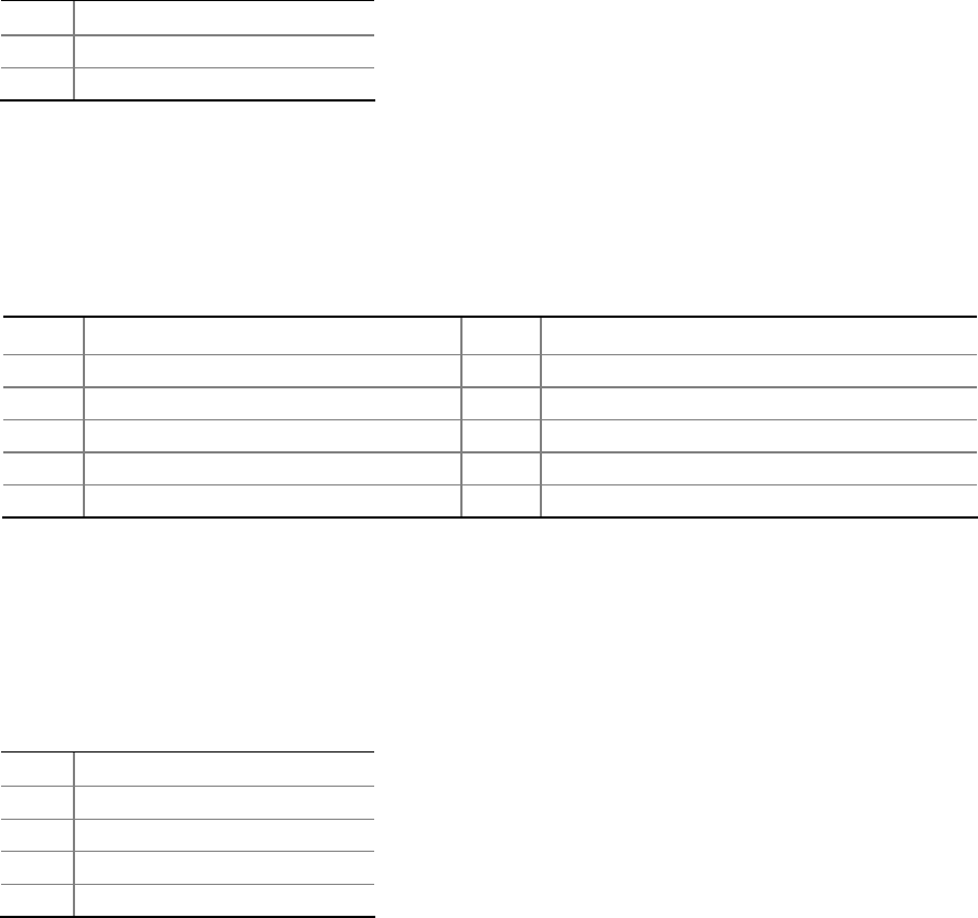
S/PDIF Header
Figure 20, G shows the location of the S/PDIF output header. Table 14 shows the pin
assignments and signal names for the S/PDIF output header.
Table 14. S/PDIF Header Signal Names
Pin Description
1 Ground
2 S/PDIF Out
3 Key (no pin)
4 +5 VDC