
Product guide
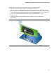
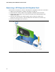


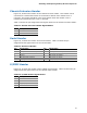


Table Of Contents
- Intel® Desktop Board DH57JG Product Guide
- Revision History
- Preface
- Contents
- 1 Desktop Board Features
- 2 Installing and Replacing Desktop Board Components
- Before You Begin
- Installation Precautions
- Installing the I/O Shield
- Installing and Removing the Desktop Board
- Installing and Removing a Processor
- Installing and Removing System Memory
- Installing and Removing PCI Express x16 Graphics Cards
- Connecting Serial ATA (SATA) Cables
- Connecting to the Internal Headers
- Connecting to the Audio System
- Connecting Chassis Fan and Power Supply Cables
- Setting the BIOS Configuration Jumper
- Clearing Passwords
- Replacing the Battery
- 3 Updating the BIOS
- A Error Messages and Indicators
- B Regulatory Compliance
Intel Desktop Board DH57JG Product Guide
42
Removing a PCI Express x16 Graphics Card
Follow these instructions to remove a PCI Express x16 graphics card from a connector:
1. Observe the precautions in "Before You Begin" on page 27.
2. Di
sconnect the monitor cable from the graphics card back panel connector.
3. Remove the screw (Figure 18, A) that secures the card’s metal bracket to the
chassis bac
k panel.
4. Push the card ejector lever down using the tip of a pencil or similar tool
(Figure 18, B) in the notch. This will release the card from the connector (C).
5. P
ull the card straight up to remove it.
Figure 18. Removing a PCI Express x16 Graphics Card