
Product guide
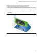
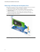
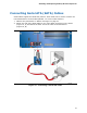
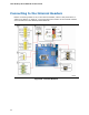


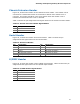


Table Of Contents
- Intel® Desktop Board DH57JG Product Guide
- Revision History
- Preface
- Contents
- 1 Desktop Board Features
- 2 Installing and Replacing Desktop Board Components
- Before You Begin
- Installation Precautions
- Installing the I/O Shield
- Installing and Removing the Desktop Board
- Installing and Removing a Processor
- Installing and Removing System Memory
- Installing and Removing PCI Express x16 Graphics Cards
- Connecting Serial ATA (SATA) Cables
- Connecting to the Internal Headers
- Connecting to the Audio System
- Connecting Chassis Fan and Power Supply Cables
- Setting the BIOS Configuration Jumper
- Clearing Passwords
- Replacing the Battery
- 3 Updating the BIOS
- A Error Messages and Indicators
- B Regulatory Compliance
Installing and Replacing Desktop Board Components
41
Follow these instructions to install a PCI Express x16 graphics card:
1. Observe the precautions in "Before You Begin" on page 27.
2. Place the card in the PCI E
xpress x16 connector (Figure 17, A) and press down on
t
he card until it is completely seated in the connector and the card retention notch
on the card snaps into place around the retention mechanism pin on the connector.
3. Secure the card’s metal bracket to the chassis back panel with a screw
(Figure 17, B).
4. Con
nect a monitor to the graphics card according to the manufacturer’s
instructions.
Figure 17. Installing a PCI Express x16 Graphics Card