
Product guide


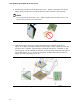


Table Of Contents
- Intel® Desktop Board DH57JG Product Guide
- Revision History
- Preface
- Contents
- 1 Desktop Board Features
- 2 Installing and Replacing Desktop Board Components
- Before You Begin
- Installation Precautions
- Installing the I/O Shield
- Installing and Removing the Desktop Board
- Installing and Removing a Processor
- Installing and Removing System Memory
- Installing and Removing PCI Express x16 Graphics Cards
- Connecting Serial ATA (SATA) Cables
- Connecting to the Internal Headers
- Connecting to the Audio System
- Connecting Chassis Fan and Power Supply Cables
- Setting the BIOS Configuration Jumper
- Clearing Passwords
- Replacing the Battery
- 3 Updating the BIOS
- A Error Messages and Indicators
- B Regulatory Compliance
Installing and Replacing Desktop Board Components
37
Removing the Processor
For instructions on how to remove the processor fan heat sink and processor, refer to
the processor installation manual.
Installing and Removing System Memory
NOTE
To be fully compliant with all applicable Intel SDRAM memory specifications, the board
requires DIMMs that support the Serial Presence Detect (SPD) data structure.
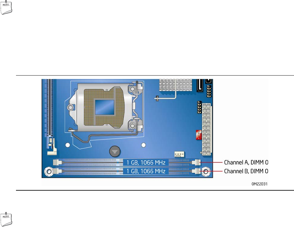
The desktop board has two 240-pin DDR3 DIMM sockets providing Channel A and
Channel B. For dual-channel performance, install a matched pair of DIMMs equal in
speed and size (see Figure 14).
Figure 14. Dual Channel Memory Configuration Example
NOTE
All other memory configurations will result in single-channel memory operation.