
Product guide

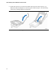

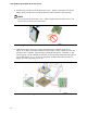


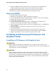
Table Of Contents
- Intel® Desktop Board DH57JG Product Guide
- Revision History
- Preface
- Contents
- 1 Desktop Board Features
- 2 Installing and Replacing Desktop Board Components
- Before You Begin
- Installation Precautions
- Installing the I/O Shield
- Installing and Removing the Desktop Board
- Installing and Removing a Processor
- Installing and Removing System Memory
- Installing and Removing PCI Express x16 Graphics Cards
- Connecting Serial ATA (SATA) Cables
- Connecting to the Internal Headers
- Connecting to the Audio System
- Connecting Chassis Fan and Power Supply Cables
- Setting the BIOS Configuration Jumper
- Clearing Passwords
- Replacing the Battery
- 3 Updating the BIOS
- A Error Messages and Indicators
- B Regulatory Compliance
Installing and Replacing Desktop Board Components
35
7. Lower the load plate over the processor while leaving the socket lever in the open
position (Figure 11).
Figure 11. Lower the Load Plate
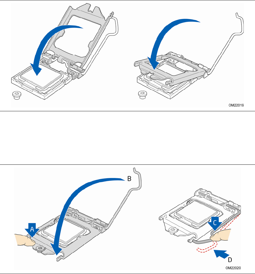
8. Lower the socket lever (Figure 12, B) while making sure that the front edge of the
load plate slides under the shoulder screw cap as the lever is lowered
(Figure 12, A). Latch the socket lever under the load plate tab (Figure 12, C, D).
Figure 12. Secure the Load Plate in Place