
Product guide


Table Of Contents
- Intel® Desktop Board DH57JG Product Guide
- Revision History
- Preface
- Contents
- 1 Desktop Board Features
- 2 Installing and Replacing Desktop Board Components
- Before You Begin
- Installation Precautions
- Installing the I/O Shield
- Installing and Removing the Desktop Board
- Installing and Removing a Processor
- Installing and Removing System Memory
- Installing and Removing PCI Express x16 Graphics Cards
- Connecting Serial ATA (SATA) Cables
- Connecting to the Internal Headers
- Connecting to the Audio System
- Connecting Chassis Fan and Power Supply Cables
- Setting the BIOS Configuration Jumper
- Clearing Passwords
- Replacing the Battery
- 3 Updating the BIOS
- A Error Messages and Indicators
- B Regulatory Compliance
Installing and Replacing Desktop Board Components
33
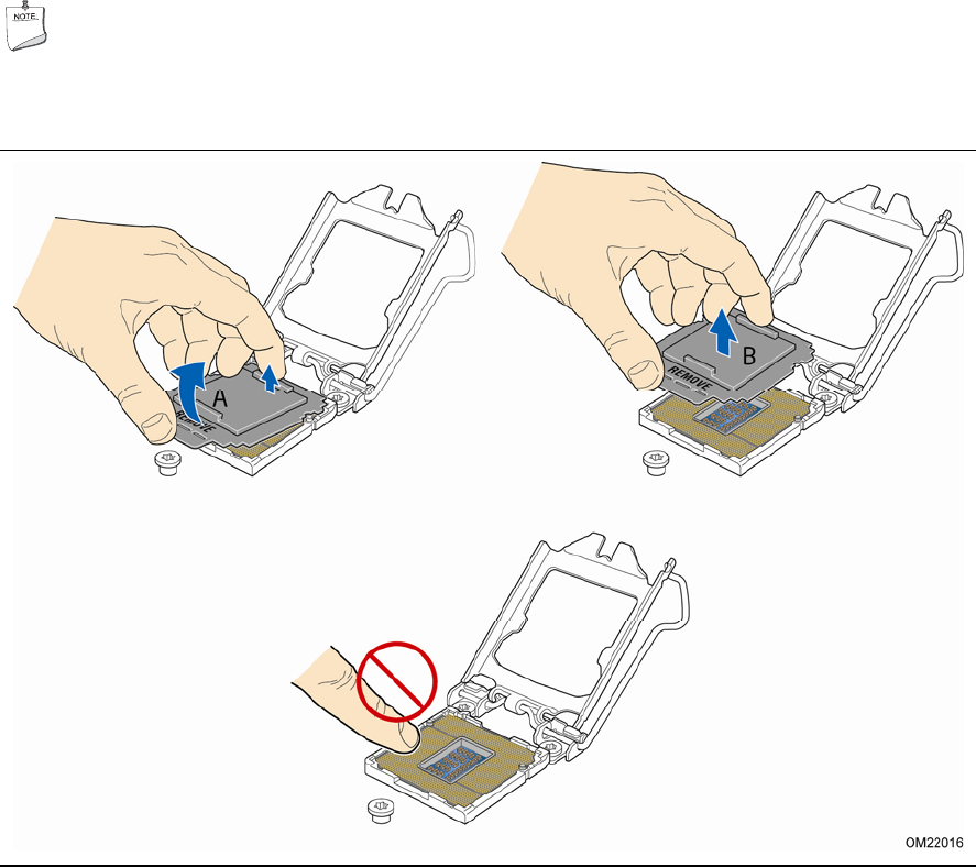
4. Remove the protective socket cover from the socket by placing your thumb against
the front edge of the cover and resting your index finger on the rear grip
(Figure 8, A). Lift the front edge of the socket to disengage the cover from the
socket and lift the
cover up and away from the socket (Figure 8, B). Do not touch
the socket contacts.
NOTE
Do not discard the socket cover; save it for possible future use. Always replace
the socket cover if you remove the processor from the socket.
Figure 8. Remove the Socket Cover