
Product guide

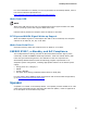
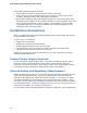

Table Of Contents
- Intel® Desktop Board DH57JG Product Guide
- Revision History
- Preface
- Contents
- 1 Desktop Board Features
- 2 Installing and Replacing Desktop Board Components
- Before You Begin
- Installation Precautions
- Installing the I/O Shield
- Installing and Removing the Desktop Board
- Installing and Removing a Processor
- Installing and Removing System Memory
- Installing and Removing PCI Express x16 Graphics Cards
- Connecting Serial ATA (SATA) Cables
- Connecting to the Internal Headers
- Connecting to the Audio System
- Connecting Chassis Fan and Power Supply Cables
- Setting the BIOS Configuration Jumper
- Clearing Passwords
- Replacing the Battery
- 3 Updating the BIOS
- A Error Messages and Indicators
- B Regulatory Compliance
Intel Desktop Board DH57JG Product Guide
30
Installing and Removing the Desktop Board
CAUTION
Only qualified technical personnel should perform this procedure. Disconnect the
computer from its power source before performing the procedures described here.
Failure to disconnect the power before you open the computer can result in personal
injury or equipment damage.
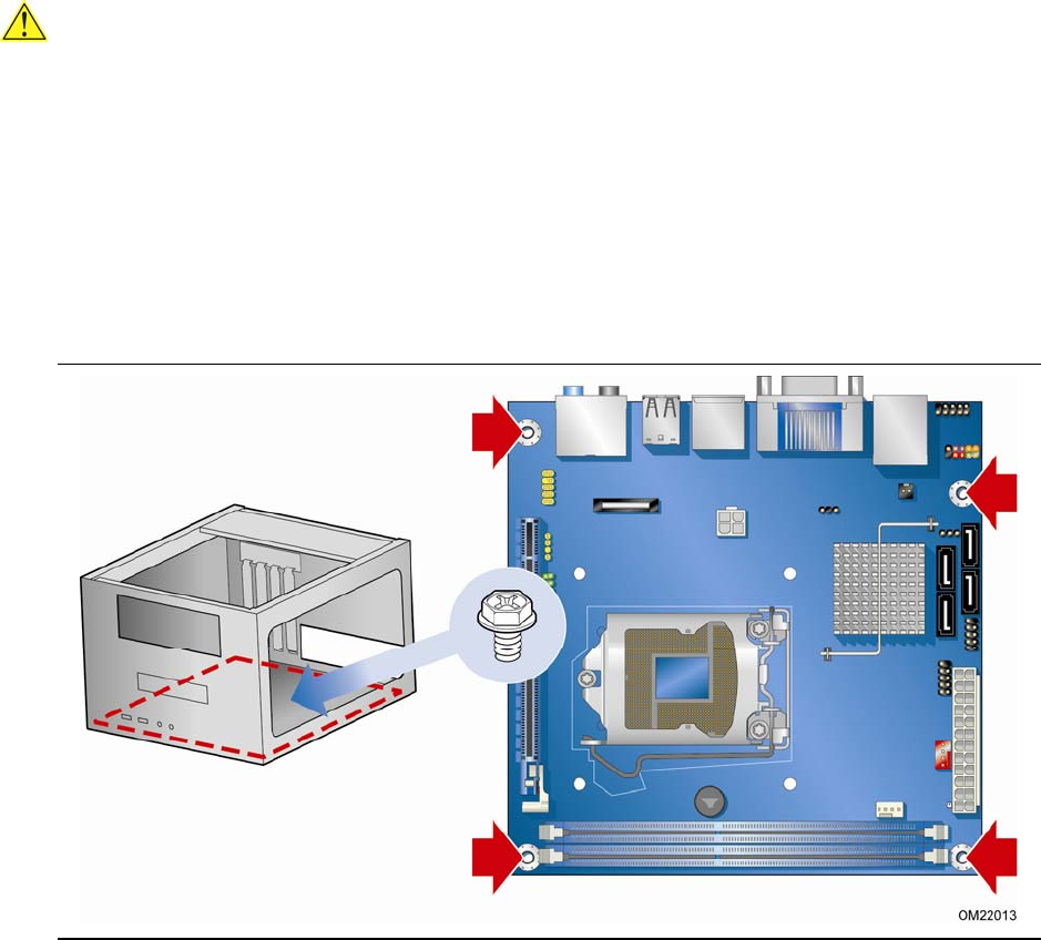
Refer to your chassis manual for instructions on installing and removing the Desktop
Board.
Figure 5 shows the location of the mounti
ng screw holes for Intel Desktop Board
DH57JG.
Figure 5. Intel Desktop Board DH57JG Mounting Screw Hole Locations