
Product guide

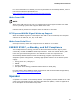
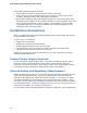

Table Of Contents
- Intel® Desktop Board DH57JG Product Guide
- Revision History
- Preface
- Contents
- 1 Desktop Board Features
- 2 Installing and Replacing Desktop Board Components
- Before You Begin
- Installation Precautions
- Installing the I/O Shield
- Installing and Removing the Desktop Board
- Installing and Removing a Processor
- Installing and Removing System Memory
- Installing and Removing PCI Express x16 Graphics Cards
- Connecting Serial ATA (SATA) Cables
- Connecting to the Internal Headers
- Connecting to the Audio System
- Connecting Chassis Fan and Power Supply Cables
- Setting the BIOS Configuration Jumper
- Clearing Passwords
- Replacing the Battery
- 3 Updating the BIOS
- A Error Messages and Indicators
- B Regulatory Compliance
Intel Desktop Board DH57JG Product Guide
24
The Desktop Board supports the PCI Bus Power Management Interface Specification.
Add-in cards that support this specification can participate in power management and
can be used to wake the computer.
The use of Instantly Available PC technology requires operating system support and
PCI 2.2 compliant add-in cards, PCI Express add-in cards, and drivers.
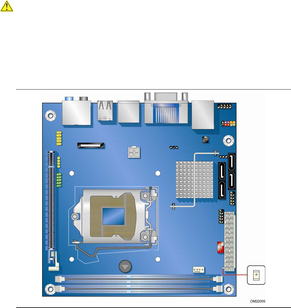
+5 V Standby Power Indicator LED
CAUTION
If the AC power has been switched off and the standby power indicator is still lit,
disconnect the power cord before installing or removing any devices connected to the
board. Failure to do so could damage the board and any attached devices.
The Desktop Board’s standby power indicator, shown in Figure 3, is lit when there is
standby power still present on the board even when the computer appears to be off.
For example, when this green LED is lit, standby power is still present at the memory
module sockets and the PCI Express connector.
Figure 3. Location of the Standby Power Indicator