
Product guide
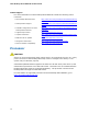

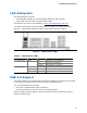
Table Of Contents
- Intel® Desktop Board DH57JG Product Guide
- Revision History
- Preface
- Contents
- 1 Desktop Board Features
- 2 Installing and Replacing Desktop Board Components
- Before You Begin
- Installation Precautions
- Installing the I/O Shield
- Installing and Removing the Desktop Board
- Installing and Removing a Processor
- Installing and Removing System Memory
- Installing and Removing PCI Express x16 Graphics Cards
- Connecting Serial ATA (SATA) Cables
- Connecting to the Internal Headers
- Connecting to the Audio System
- Connecting Chassis Fan and Power Supply Cables
- Setting the BIOS Configuration Jumper
- Clearing Passwords
- Replacing the Battery
- 3 Updating the BIOS
- A Error Messages and Indicators
- B Regulatory Compliance
Desktop Board Features
19
LAN Subsystem
The LAN subsystem includes:
• Intel 82578DC Gigabit (10/100/1000 Mb/s) Ethernet LAN controller
• RJ-45 LAN connector with integrated status LEDs
LAN software and drivers are available at http://downloadcenter.intel.com/
.
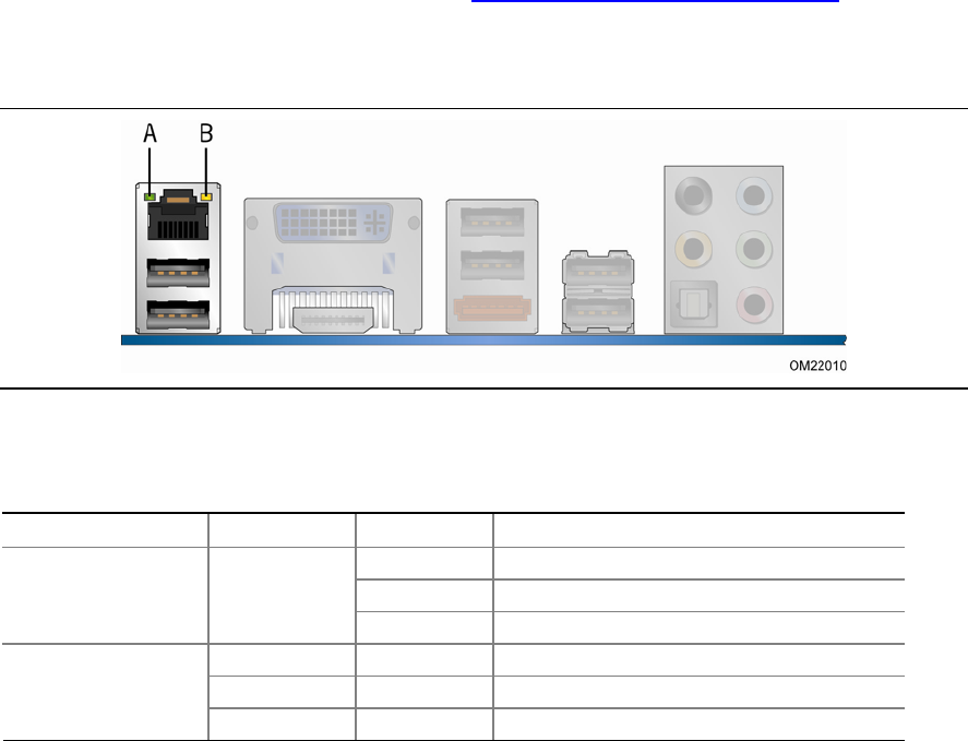
Two LEDs are built into the RJ-45 LAN connector located on the back panel (see
Figure 2). These LEDs indicate the status of the LAN as shown in Table 6.
Figure 2. LAN Connector LEDs
Table 6. LAN Connector LEDs
LED LED Color LED State Indicates
A (Link/Activity) Off LAN link is not established
Green
On LAN link is established
Blinking LAN activity is occurring
N/A Off 10 Mb/s data rate
Green On 100 Mb/s data rate
B (Link Speed)
Yellow On 1000 Mb/s data rate
USB 2.0 Support
The board supports up to twelve USB 2.0 ports provided by two EHCI host controllers
in the Intel H57 PCH that allow the use of EHCI-compatible drivers.
The port arrangement is as follows:
• Six ports via stacked back panel connectors
• Six front panel ports via three dual-port internal headers
USB 2.0 support requires both an operating system and drivers that fully support
USB 2.0 transfer rates.