
Product guide
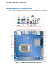
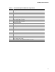

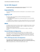
Table Of Contents
- Intel® Desktop Board DH57JG Product Guide
- Revision History
- Preface
- Contents
- 1 Desktop Board Features
- 2 Installing and Replacing Desktop Board Components
- Before You Begin
- Installation Precautions
- Installing the I/O Shield
- Installing and Removing the Desktop Board
- Installing and Removing a Processor
- Installing and Removing System Memory
- Installing and Removing PCI Express x16 Graphics Cards
- Connecting Serial ATA (SATA) Cables
- Connecting to the Internal Headers
- Connecting to the Audio System
- Connecting Chassis Fan and Power Supply Cables
- Setting the BIOS Configuration Jumper
- Clearing Passwords
- Replacing the Battery
- 3 Updating the BIOS
- A Error Messages and Indicators
- B Regulatory Compliance

Desktop Board Features
13
Table 2. Intel Desktop Board DH57JG Components
Label Description
A Back panel connectors
B Front panel USB 2.0 header
C Front panel header
D Chassis intrusion header
E Alternate front panel power LED header
F BIOS configuration jumper block
G Serial ATA connectors (4)
H Front panel USB 2.0 header
I Front panel USB 2.0 header
J Chassis fan header
K Main power connector (2 x 12 pin)
L Processor fan header
M Standby power indicator LED
N Channel A DIMM 0 socket
O Channel B DIMM 0 socket
P Speaker
Q Processor socket
R Serial port header
S PCI Express 2.0 x16 add-in card connector
T S/PDIF header
U Battery
V Front panel audio header
W 12 V processor core voltage connector (2 x 2 pin)