Intel® Desktop Board DH55PJ Product Guide Order Number: E93622-001
Revision History Revision -001 Revision History First release of the Intel® Desktop Board DH55PJ Product Guide Date April 2010 Disclaimer INFORMATION IN THIS DOCUMENT IS PROVIDED IN CONNECTION WITH INTEL® PRODUCTS. NO LICENSE, EXPRESS OR IMPLIED, BY ESTOPPEL OR OTHERWISE, TO ANY INTELLECTUAL PROPERTY RIGHTS IS GRANTED BY THIS DOCUMENT.
Preface This Product Guide gives information about board layout, component installation, BIOS update, and regulatory requirements for Intel® Desktop Board DH55PJ. Intended Audience The Product Guide is intended for technically qualified personnel. It is not intended for general audiences. Use Only for Intended Applications All Intel Desktop Boards are evaluated as Information Technology Equipment (I.T.E.
Intel Desktop Board DH55PJ Product Guide Terminology The table below gives descriptions of some common terms used in the product guide.
Contents 1 Desktop Board Features Supported Operating Systems..............................................................................11 Desktop Board Components.................................................................................12 Processor..........................................................................................................14 Intel® H55 Express Chipset .................................................................................14 Main Memory......................
Intel Desktop Board DH55PJ Product Guide Installing and Removing the Desktop Board ...........................................................28 Installing and Removing a Processor .....................................................................29 Installing a Processor ..................................................................................29 Installing a Processor Fan Heat Sink ..............................................................34 Connecting the Processor Fan Heat Sink Cable....
Contents Canadian Department of Communications Compliance Statement ......................72 Japan VCCI Statement ................................................................................72 Korea Class B Statement .............................................................................73 Ensure Electromagnetic Compatibility (EMC) Compliance ..................................73 Product Certifications..........................................................................................
Intel Desktop Board DH55PJ Product Guide Tables 1. 2. 3. 4. 5. 6. 7. 8. 9. 10. 11. 12. 13. 14. 15. 16. 17. 18. 19. viii Feature Summary.......................................................................................... 9 Intel Desktop Board DH55PJ Components ........................................................13 LAN Connector LEDs .....................................................................................18 Front Panel Audio Signal Names for Intel HD Audio............................
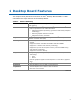
1 Desktop Board Features This chapter briefly describes the features of Intel® Desktop Board DH55PJ. Table 1 summarizes the major features of the Desktop Board. Table 1. Feature Summary Form Factor MicroATX (243.84 millimeters [9.60 inches] x 243.84 millimeters [9.
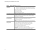
Intel Desktop Board DH55PJ Product Guide Table 1. Feature Summary (continued) Peripheral Interfaces • Twelve USB 2.0 ports: ― Six ports are implemented with stacked back panel connectors ― Six ports are implemented with three dual-port internal headers • Four Serial ATA (SATA) 3.
Desktop Board Features Supported Operating Systems The Desktop Board supports the following operating systems: • • • • • • • • • • • • • • • • • • Microsoft Microsoft Microsoft Microsoft Microsoft Microsoft Microsoft Microsoft Microsoft Microsoft Microsoft Microsoft Microsoft Microsoft Microsoft Microsoft Microsoft Microsoft Windows* 7 Ultimate 64-bit edition Windows 7 Ultimate 32-bit edition Windows 7 Home Premium 64-bit edition Windows 7 Home Premium 32-bit edition Windows 7 Home Basic 64-bit edition W
Intel Desktop Board DH55PJ Product Guide Desktop Board Components Figure 1 shows the approximate location of the major components on Intel Desktop Board DH55PJ. Figure 1.
Desktop Board Features Table 2. Intel Desktop Board DH55PJ Components Label Description A PCI bus add-in card connector B PCI Express 2.0 x1 add-in card connector C Battery D PCI Express 2.0 x1 add-in card connector E PCI Express 2.
Intel Desktop Board DH55PJ Product Guide Online Support For more information on Intel Desktop Board DH55PJ consult the following online resources: • Intel Desktop Board DH55PJ http://www.intel.com/products/motherboard/DH55PJ/i ndex.htm • Desktop Board Support http://support.intel.com/support/motherboards/deskt op/DH55PJ • Available configurations for Intel Desktop Board DH55PJ http://www.intel.com/products/motherboard/DH55PJ/i ndex.htm • Supported processors http://processormatch.intel.
Desktop Board Features Main Memory NOTE To be fully compliant with all applicable Intel ® SDRAM memory specifications, the board should be populated with DIMMs that support the Serial Presence Detect (SPD) data structure. If your memory modules do not support SPD, you will see a notification to this effect on the screen at power up. The BIOS will attempt to configure the memory controller for normal operation.
Intel Desktop Board DH55PJ Product Guide Digital Visual Interface (DVI-D) The DVI-D port supports digital DVI displays. The maximum supported resolution is 1920 x 1200 at 60 Hz refresh (WUXGA). The DVI-D port is compliant with the DVI 1.0 specification. The DVI-D port is only enabled for POST when there is no monitor attached to the VGA connector.
Desktop Board Features The onboard audio headers include the following: • • • Front panel audio (a 2 x 5 pin header that provides headphone and mic in signals for front panel audio connectors) S/PDIF audio header (1 x 4 pin header) Internal mono speaker header (1 x 2 pin header) Front panel headphone output is supported by a separate audio channel pair, allowing multi-streaming audio configurations such as simultaneous 6-channel (5.
Intel Desktop Board DH55PJ Product Guide Table 3. LAN Connector LEDs LED LED Color LED State Indicates A (Link/Activity) Green Off LAN link is not established On LAN link is established Blinking LAN activity is occurring Off 10 Mb/s data rate B (Link Speed) N/A Green On 100 Mb/s data rate Yellow On 1000 Mb/s data rate USB 2.0 Support The board supports up to twelve USB 2.0 ports provided by two EHCI host controllers in the PCH that allow the use of EHCI-compatible drivers.
Desktop Board Features Legacy I/O The board’s Legacy I/O Controller provides the following legacy features: • • • • • • One serial port header One parallel port header with Extended Capabilities Port (ECP) and Enhanced Parallel Port (EPP) support Serial IRQ interface compatible with serialized IRQ support for PCI Conventional bus systems PS/2-style keyboard/mouse interface Intelligent power management, including a programmable wake-up event interface PCI Conventional bus power management support The BIOS
Intel Desktop Board DH55PJ Product Guide Security Passwords The BIOS includes security features that restrict whether the BIOS Setup program can be accessed and who can boot the computer. A supervisor password and a user password can be set for the BIOS Setup and for booting the computer, with the following restrictions: • • • The supervisor password gives unrestricted access to view and change all Setup options.
Desktop Board Features Power Management Power management is implemented at several levels, including software support through the Advanced Configuration and Power Interface (ACPI) and the following hardware support: • • • • • • • • • • Power connectors Fan headers LAN wake capabilities Instantly Available PC technology (Suspend to RAM) +5 V standby power indicator LED Wake from USB PCI Power Management Event signal (PME#) wakeup support PCI Express WAKE# signal support Wake from PS/2 devices Wake from ser
Intel Desktop Board DH55PJ Product Guide • • • All fan headers have a +12 V DC connection (up to 12 V DC when using 3-wire chassis fans. All fan headers are controlled by Pulse Width Modulation. The front and rear chassis fans support Linear Fan Control on 3-wire fans. The Desktop Board has a 4-pin processor fan header and two 4-pin chassis fan headers compatible with 4-wire and 3-wire chassis fans.
Desktop Board Features +5 V Standby Power Indicator LED CAUTION If the AC power has been switched off and the standby power indicator is still lit, disconnect the power cord before installing or removing any devices connected to the board. Failure to do so could damage the board and any attached devices. The Desktop Board’s standby power indicator, shown in Figure 3, is lit when there is standby power still present on the board even when the computer appears to be off.
Intel Desktop Board DH55PJ Product Guide PCI Express WAKE# Signal Wake-up Support When the WAKE# signal on a PCI Express bus add-in card is asserted, the computer wakes from an ACPI S1, S3, S4, or S5 state. Wake from PS/2 Devices PS/2 device activity can wake the computer from an ACPI S1, S3, S4, or S5 state. When the computer is in the S4 state, any key can be used to wake the computer provided a supported operating system is installed.
2 Installing and Replacing Desktop Board Components This chapter tells you how to: • • • • • • • • • • • • Install the I/O shield Install and remove the Desktop Board Install and remove a processor Install and remove memory Install and remove a PCI Express x16 card Connect Serial ATA cables Connect to the internal headers and connectors Connect to the audio system Connect chassis fan and power supply cables Set the BIOS configuration jumper Clear passwords Replace the battery Before You Begin CAUTIONS The
Intel Desktop Board DH55PJ Product Guide Installation Precautions When you install and test the Intel Desktop Board, observe all warnings and cautions in the installation instructions.
Installing and Replacing Desktop Board Components Installing the I/O Shield The Desktop Board comes with an I/O shield. When installed in the chassis, the shield blocks radio frequency transmissions, protects internal components from dust and foreign objects, and promotes correct airflow within the chassis. Install the I/O shield before installing the Desktop Board in the chassis. Place the shield inside the chassis as shown in Figure 4. Press the shield into place so that it fits tightly and securely.
Intel Desktop Board DH55PJ Product Guide Installing and Removing the Desktop Board CAUTION Only qualified technical personnel should perform this procedure. Disconnect the computer from its power source before performing the procedures described here. Failure to disconnect the power before you open the computer can result in personal injury or equipment damage. Refer to your chassis manual for instructions on installing and removing the Desktop Board.
Installing and Replacing Desktop Board Components Installing and Removing a Processor Instructions on how to install the processor on the Desktop Board are given below. Installing a Processor CAUTION Before installing or removing a processor, make sure the AC power has been removed by unplugging the power cord from the computer; the standby power LED should not be lit (see Figure 3 on page 23). Failure to do so could damage the processor and the board. To install a processor, follow these instructions: 1.
Intel Desktop Board DH55PJ Product Guide 3. Rotate the socket lever to lift the load plate away from the socket (Figure 7, A). Make sure that the load plate is in the fully open position (Figure 7, B) while being careful not to damage adjacent components. Figure 7.
Installing and Replacing Desktop Board Components 4. Remove the protective socket cover from the socket by placing your thumb against the front edge of the cover and resting your index finger on the rear grip (Figure 8, A). Lift the front edge of the socket to disengage the cover from the socket and lift the cover up and away from the socket (Figure 8, B). Do not touch the socket contacts. NOTE Do not discard the socket cover; save it for possible future use.
Intel Desktop Board DH55PJ Product Guide 5. Remove the processor from its protective cover. Hold the processor only at the edges, being careful not to touch the bottom of the processor (see Figure 9). NOTE Do not discard the processor cover. Always replace the processor cover if you remove the processor from the socket. Figure 9. Remove the Processor from the Protective Cover 6.
Installing and Replacing Desktop Board Components 7. Lower the load plate over the processor while leaving the socket lever in the open position (Figure 11). Figure 11. Lower the Load Plate 8. Lower the socket lever (Figure 12, B) while making sure that the front edge of the load plate slides under the shoulder screw cap as the lever is lowered (Figure 12, A). Latch the socket lever under the load plate tab (Figure 12, C, D). Figure 12.
Intel Desktop Board DH55PJ Product Guide Installing a Processor Fan Heat Sink Intel Desktop Board DH55PJ has mounting holes for a processor fan heat sink. For instructions on how to attach the processor fan heat sink to the Desktop Board, refer to the boxed processor manual or boxed thermal solution manual. Connecting the Processor Fan Heat Sink Cable Connect the processor fan heat sink power cable to the 4-pin processor fan header (see Figure 13).
Installing and Replacing Desktop Board Components Installing and Removing System Memory NOTE To be fully compliant with all applicable Intel SDRAM memory specifications, the board requires DIMMs that support the Serial Presence Detect (SPD) data structure. The Desktop Board has two 240-pin DDR3 DIMM sockets providing Channel A and Channel B. For optimum dual-channel performance, install a matched pair of DIMMs equal in speed and size (see Figure 14). Figure 14.
Intel Desktop Board DH55PJ Product Guide Installing DIMMs To make sure you have the correct DIMM, place it on the illustration of the DDR3 DIMM in Figure 15. All the notches should match with the DDR3 DIMM. Figure 15.
Installing and Replacing Desktop Board Components To install a DIMM, follow these steps: 1. Observe the precautions in "Before You Begin" on page 25. 2. Turn off all peripheral devices connected to the computer. Turn off the computer and disconnect the AC power cord. 3. Remove the computer’s cover and locate the DIMM sockets (see Figure 16). 4. If a full length PCI Express graphics card is installed in the PCI Express x16 connector, remove the card to gain full access to the DIMM sockets. Figure 16.
Intel Desktop Board DH55PJ Product Guide Removing DIMMs To remove a DIMM, follow these steps: 1. 2. 3. 4. 5. 6. 7. 8. 9. Observe the precautions in "Before You Begin" on page 25. Turn off all peripheral devices connected to the computer. Turn off the computer. Remove the AC power cord from the computer. Remove the computer’s cover. If a full length PCI Express graphics card is installed in the PCI Express x16 connector, remove the card to gain access to the DIMMs.
Installing and Replacing Desktop Board Components 4. Connect a monitor to the graphics card according to the manufacturer’s instructions. Figure 17. Installing a PCI Express x16 Graphics Card Removing a PCI Express x16 Graphics Card Follow these instructions to remove a PCI Express x16 graphics card from a connector: 1. Observe the precautions in "Before You Begin" on page 25. 2. Disconnect the monitor cable from the graphics card back panel connector. 3.
Intel Desktop Board DH55PJ Product Guide Figure 18.
Installing and Replacing Desktop Board Components Connecting Serial ATA (SATA) Cables SATA cables support the Serial ATA protocol. Each cable can be used to connect one internal SATA drive to the Desktop Board. For correct cable function: 1. Observe the precautions in “Before You Begin” on page 25. 2. Attach one end of the SATA cable to one of the SATA connectors on the board (Figure 19, A) and attach the other end of the cable to the SATA drive (Figure 19, B). Figure 19.
Intel Desktop Board DH55PJ Product Guide Connecting to the Internal Headers Before connecting cables to any of the internal headers, observe the precautions in “Before You Begin” on page 25. Figure 20 shows the location of the internal headers and connectors on Intel Desktop Board DH55PJ. Figure 20.
Installing and Replacing Desktop Board Components Front Panel Audio Header The front panel audio header shown in Figure 20, A supports both Intel High Definition (HD) Audio and AC ’97 Audio. Table 4 shows the pin assignments and signal names for HD Audio and Table 5 shows the pin assignments and signal names for AC ’97 Audio. Table 4.
Intel Desktop Board DH55PJ Product Guide S/PDIF Header Figure 20, C shows the location of the S/PDIF output header. Table 7 shows the pin assignments and signal names for the S/PDIF output header. Table 7. S/PDIF Header Signal Names Pin Description 1 Ground 2 S/PDIF Out 3 Key (no pin) 4 +5 VDC Parallel Port Header Figure 20, D shows the location of the parallel port header. Table 8 shows the pin assignments and signal names for the parallel port header. Table 8.
Installing and Replacing Desktop Board Components Pin Standard Signal Name ECP Signal Name EPP Signal Name 23 PERROR PE, ACKREVERSE# PE 24 GROUND GROUND GROUND 25 SELECT SELECT SELECT 26 KEY (no pin) KEY (no pin) KEY (no pin) Alternate Front Panel Power LED Header Figure 20, E shows the location of the alternate front panel power LED header. Pins 1 and 3 of this header duplicate the signals on pins 2 and 4 of the front panel header.
Intel Desktop Board DH55PJ Product Guide Front Panel USB 2.0 Headers Figure 20, G shows the location of the front panel USB 2.0 headers and Table 11 shows the pin assignments and signal names. Table 11. USB 2.
Installing and Replacing Desktop Board Components Serial Header Figure 20, H shows the location of the serial header. Table 12 shows the pin assignments and signal names for the serial header. Table 12.
Intel Desktop Board DH55PJ Product Guide Connecting Chassis Fan and Power Supply Cables Connecting Chassis Fan Cables Connect chassis fan cables to the chassis fan headers on the Desktop Board. Figure 22 shows the location of the chassis fan headers. Figure 22.
Installing and Replacing Desktop Board Components Connecting Power Supply Cables CAUTION Failure to use an appropriate power supply and/or not connecting the 12 V power connector (Figure 23, A) to the Desktop Board may result in damage to the board or the system may not function properly. Figure 23 shows the location of the power connectors. The 2 x 12 pin main power connector (Figure 23, B) is backwards compatible with ATX12V power supplies with 2 x 10 connectors.
Intel Desktop Board DH55PJ Product Guide Setting the BIOS Configuration Jumper NOTE Always turn off the power and unplug the power cord from the computer before moving the jumper. Moving the jumper with the power on may result in unreliable computer operation. Figure 24 shows the location of the Desktop Board’s BIOS configuration jumper block. Figure 24.
Installing and Replacing Desktop Board Components The three-pin BIOS jumper block enables board configuration to be done in the BIOS Setup program. Table 13 shows the jumper settings for the BIOS Setup program modes. Table 13. Jumper Settings for the BIOS Setup Program Modes Jumper Setting Mode Description Normal (default) (1-2) The BIOS uses the current configuration and passwords for booting. Configure (2-3) After the Power-On Self-Test (POST) runs, the BIOS displays the Maintenance Menu.
Intel Desktop Board DH55PJ Product Guide 8. Use the arrow keys to select Clear Passwords. Press and Setup displays a pop-up screen requesting that you confirm clearing the password. Select Yes and press . Setup displays the maintenance menu again. 9. Press to save the current values and exit Setup. 10. Turn off the computer. Disconnect the computer’s power cord from the AC power source. 11. Remove the computer cover. 12.
Installing and Replacing Desktop Board Components OBS! Det kan oppstå eksplosjonsfare hvis batteriet skiftes ut med feil type. Brukte batterier bør kastes i henhold til gjeldende miljølovgivning. VIKTIGT! Risk för explosion om batteriet ersätts med felaktig batterityp. Batterier ska kasseras enligt de lokala miljövårdsbestämmelserna. VARO Räjähdysvaara, jos pariston tyyppi on väärä. Paristot on kierrätettävä, jos se on mahdollista.
Intel Desktop Board DH55PJ Product Guide AŚCIAROŽZNAŚĆ Існуе рызыка выбуху, калі заменены акумулятар неправільнага тыпу. Акумулятары павінны, па магчымасці, перепрацоўвацца. Пазбаўляцца ад старых акумулятараў патрэбна згодна з мясцовым заканадаўствам па экалогіі. UPOZORNÌNÍ V případě výměny baterie za nesprávný druh může dojít k výbuchu. Je-li to možné, baterie by měly být recyklovány. Baterie je třeba zlikvidovat v souladu s místními předpisy o životním prostředí.
Installing and Replacing Desktop Board Components ВНИМАНИЕ При использовании батареи несоответствующего типа существует риск ее взрыва. Батареи должны быть утилизированы по возможности. Утилизация батарей должна проводится по правилам, соответствующим местным требованиям. UPOZORNENIE Ak batériu vymeníte za nesprávny typ, hrozí nebezpečenstvo jej výbuchu. Batérie by sa mali podľa možnosti vždy recyklovať.
Intel Desktop Board DH55PJ Product Guide 56
Installing and Replacing Desktop Board Components To replace the battery, follow these steps: 1. Observe the precautions in "Before You Begin" (see page 25). 2. Turn off all peripheral devices connected to the computer. Disconnect the computer’s power cord from the AC power source (wall outlet or power adapter). 3. Remove the computer cover. 4. Locate the battery on the board (see Figure 25). 5. With a medium flat-bladed screwdriver, gently pry the battery free from its connector.
Intel Desktop Board DH55PJ Product Guide 58
3 Updating the BIOS The BIOS Setup program can be used to view and change the BIOS settings for the computer. You can access the BIOS Setup program by pressing the key after the Power-On Self-Test (POST) memory test begins and before the operating system boot begins. This chapter tells you how to update the BIOS by either using the Intel Express BIOS Update utility or the Iflash Memory Update utility, and how to recover the BIOS if an update fails.
Intel Desktop Board DH55PJ Product Guide Updating the BIOS with the ISO Image BIOS Update File or the Iflash Memory Update Utility You can use the information in this section to update the BIOS using either the Iflash Memory Update Utility or the ISO Image BIOS update file. Obtaining the BIOS Update File You can update to a new version of the BIOS by using the ISO Image BIOS update file (recommended), or Iflash BIOS update file.
Updating the BIOS CAUTION Do not interrupt the process or the system may not function properly. Follow these instructions to upgrade the BIOS using the ISO Image BIOS file: 1. Download the ISO Image BIOS file. 2. Using software capable of writing an ISO image file to CD, burn the data to a blank CD. NOTE Copying the ISO Image BIOS file to CD will not work. The completed CD should contain multiple files and a directory. 3.
Intel Desktop Board DH55PJ Product Guide CAUTION Do not interrupt the process or the system may not function properly. 1. Uncompress the BIOS update file and copy the .BIO file, IFLASH.EXE, and .ITK file (optional) to a bootable USB flash drive or other bootable USB media. 2. Configure the BIOS or use the F10 option during POST to boot to the USB device. 3. Manually run the IFLASH.EXE file from the USB device and manually update the BIOS.
A Error Messages and Indicators Intel Desktop Board DH55PJ reports POST errors in two ways: • • By sounding a beep code and blinking the front panel power LED By displaying an error message on the monitor BIOS Error Codes Whenever a recoverable error occurs during POST, the BIOS causes the board’s speaker to beep and the front panel power LED to blink an error message indicating the problem (see Table 14). Table 14. BIOS Beep Codes Type Pattern Frequency/Comments F2 Setup/F10 Boot Menu Prompt One 0.
Intel Desktop Board DH55PJ Product Guide Table 15. Front-panel Power LED Blink Codes Type Pattern F2 Setup/F10 Boot Menu Prompt None Note BIOS update in progress Off when the update begins, then on for 0.5 seconds, then off for 0.5 seconds. The pattern repeats until the BIOS update is complete. Video error (no addin graphics card installed) On-off (1.0 second each) two times, then a 2.5-second pause (off), the entire pattern repeats (blink and pause) until the system is powered off.
B Regulatory Compliance This appendix contains the following regulatory compliance information for Intel Desktop Board DH55PJ: • • • • • Safety standards European Union Declaration of Conformity statement Product Ecology statements Electromagnetic Compatibility (EMC) regulations Product certifications Safety Standards Intel Desktop Board DH55PJ complies with the safety standards stated in Table 17 when correctly installed in a compatible host system. Table 17.
Intel Desktop Board DH55PJ Product Guide European Union Declaration of Conformity Statement We, Intel Corporation, declare under our sole responsibility that the product Intel® Desktop Board DH55PJ is in conformity with all applicable essential requirements necessary for CE marking, following the provisions of the European Council Directives 2004/108/EC (EMC Directive), 2006/95/EC (Low Voltage Directive), and 2002/95/EC (ROHS Directive).
Regulatory Compliance Polski Niniejszy produkt jest zgodny z postanowieniami Dyrektyw Unii Europejskiej 2004/108/EC, 206/95/EC i 2002/95/EC. Portuguese Este produto cumpre com as normas da Diretiva Européia 2004/108/EC, 2006/95/EC & 2002/95/EC. Español Este producto cumple con las normas del Directivo Europeo 2004/108/EC, 2006/95/EC & 2002/95/EC. Slovensky Tento produkt je v súlade s ustanoveniami európskych direktív 2004/108/EC, 2006/95/EC a 2002/95/EC.
Intel Desktop Board DH55PJ Product Guide Deutsch Als Teil von Intels Engagement für den Umweltschutz hat das Unternehmen das Intel Produkt-Recyclingprogramm implementiert, das Einzelhandelskunden von Intel Markenprodukten ermöglicht, gebrauchte Produkte an ausgewählte Standorte für ordnungsgemäßes Recycling zurückzugeben. Details zu diesem Programm, einschließlich der darin eingeschlossenen Produkte, verfügbaren Standorte, Versandanweisungen, Bedingungen usw., finden Sie auf der http://intel.
Regulatory Compliance Portuguese Como parte deste compromisso com o respeito ao ambiente, a Intel implementou o Programa de Reciclagem de Produtos para que os consumidores finais possam enviar produtos Intel usados para locais selecionados, onde esses produtos são reciclados de maneira adequada. Consulte o site http://intel.
Intel Desktop Board DH55PJ Product Guide China RoHS Intel Desktop Board DH55PJ is a China RoHS-compliant product. The China Ministry of Information Industry (MII) stipulates that a material Self Declaration Table (SDT) must be included in a product’s user documentation. The SDT for Intel Desktop Board DH55PJ is shown in Figure 26. Figure 26.
Regulatory Compliance EMC Regulations Intel Desktop Board DH55PJ complies with the EMC regulations stated in Table 18 when correctly installed in a compatible host system. Table 18. EMC Regulations Regulation Title FCC 47 CFR Part 15, Subpart B Title 47 of the Code of Federal Regulations, Part 15, Subpart B, Radio Frequency Devices. (USA) ICES-003 Interference-Causing Equipment Standard, Digital Apparatus.
Intel Desktop Board DH55PJ Product Guide radio or television reception, which can be determined by turning the equipment off and on, the user is encouraged to try to correct the interference by one or more of the following measures: • • • • Reorient or relocate the receiving antenna. Increase the separation between the equipment and the receiver. Connect the equipment to an outlet on a circuit other than the one to which the receiver is connected.
Regulatory Compliance Korea Class B Statement Korea Class B Statement translation: This equipment is for home use, and has acquired electromagnetic conformity registration, so it can be used not only in residential areas, but also other areas. Ensure Electromagnetic Compatibility (EMC) Compliance Before computer integration, make sure that the power supply and other modules or peripherals, as applicable, have passed Class B EMC testing and are marked accordingly.
Intel Desktop Board DH55PJ Product Guide Product Certifications Board-Level Certifications Intel Desktop Board DH55PJ has the regulatory compliance marks shown in Table 19. Table 19. Regulatory Compliance Marks Description Mark UL joint US/Canada Recognized Component mark. Includes adjacent UL file number for Intel Desktop Boards: E210882. FCC Declaration of Conformity logo mark for Class B equipment. CE mark.
Regulatory Compliance Chassis- and Component-Level Certifications Ensure that the chassis and certain components; such as the power supply, peripheral drives, wiring, and cables; are components certified for the country or market where used. Agency certification marks on the product are proof of certification. Typical product certifications include: In Europe The CE mark indicates compliance with all applicable European requirements.
Intel Desktop Board DH55PJ Product Guide 76