Intel® Desktop Board DG965SS Technical Product Specification August 2006 Order Number: D56010-001US The Intel® Desktop Board DG965SS may contain design defects or errors known as errata that may cause the product to deviate from published specifications. Current characterized errata are documented in the Intel Desktop Board DG965SS Specification Update.
Revision History Revision -001 Revision History First release of the Specification. Intel® Date Desktop Board DG965SS Technical Product August 2006 This product specification applies to only the standard Intel® Desktop Board DG965SS with BIOS identifier MQ96510A.86A. Changes to this specification will be published in the Intel Desktop Board DG965SS Specification Update before being incorporated into a revision of this document.
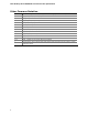
Preface This Technical Product Specification (TPS) specifies the board layout, components, connectors, power and environmental requirements, and the BIOS for the Intel® Desktop Board DG965SS. It describes the standard product and available manufacturing options. Intended Audience The TPS is intended to provide detailed, technical information about the Desktop Board DG965SS and its components to the vendors, system integrators, and other engineers and technicians who need this level of information.
Intel Desktop Board DG965SS Technical Product Specification Other Common Notation iv # Used after a signal name to identify an active-low signal (such as USBP0#) GB Gigabyte (1,073,741,824 bytes) GB/sec Gigabytes per second Gbit Gigabit (1, 073,741,824 bits) KB Kilobyte (1024 bytes) Kbit Kilobit (1024 bits) kbits/sec 1000 bits per second MB Megabyte (1,048,576 bytes) MB/sec Megabytes per second Mbit Megabit (1,048,576 bits) Mbit/sec Megabits per second xxh An address or data value
Contents 1 Product Description 1.1 Overview........................................................................................ 10 1.1.1 Feature Summary ................................................................ 10 1.1.2 Board Layout ....................................................................... 12 1.1.3 Block Diagram ..................................................................... 14 1.2 Online Support................................................................................
Intel Desktop Board DG965SS Technical Product Specification 2.6 PCI Interrupt Routing Map ................................................................ 47 2.7 Connectors and Headers................................................................... 48 2.7.1 Back Panel Connectors .......................................................... 49 2.7.2 Component-side Connectors and Headers ................................ 50 2.8 Jumper Block .....................................................................
Contents 5.1.2 5.1.3 5.1.4 5.1.5 5.2 Battery European Union Declaration of Conformity Statement ................ Product Ecology Statements................................................... EMC Regulations .................................................................. Product Certification Markings (Board Level)............................. Disposal Information............................................................. 84 86 90 91 92 Major Board Components.........................................
Intel Desktop Board DG965SS Technical Product Specification 14. 15. 16. 17. 18. 19. 20. 21. 22. 23. 24. 25. 26. 27. 28. 29. 30. 31. 32. 33. 34. 35. 36. 37. 38. 39. 40. 41. 42. 43. 44. 45. 46. 47. 48. viii Interrupts ...................................................................................... PCI Interrupt Routing Map ................................................................ Component-side Connectors and Headers Shown in Figure 16................ High Definition Audio Link Header ........
1 Product Description What This Chapter Contains 1.1 1.2 1.3 1.4 1.5 1.6 1.7 1.8 1.9 1.10 Overview...................................................................................................10 Online Support ...........................................................................................15 Processor ..................................................................................................15 System Memory ...........................................................................
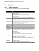
Intel Desktop Board DG965SS Technical Product Specification 1.1 Overview 1.1.1 Feature Summary Table 1 summarizes the major features of the Desktop Board DG965SS. Table 1. Feature Summary Form Factor microATX (9.60 inches by 9.60 inches [243.84 millimeters by 243.
Product Description Table 1.
Intel Desktop Board DG965SS Technical Product Specification 1.1.2 Board Layout Figure 1 shows the location of the major components. A B C D E F G H DD CC I BB J K AA Z Y L M N X W V U TS R Q P O OM18462 Figure 1. Major Board Components Table 2 lists the components identified in Figure 1.
Product Description Table 2.
Intel Desktop Board DG965SS Technical Product Specification 1.1.3 Block Diagram Figure 2 is a block diagram of the major functional areas.
Product Description 1.2 Online Support To find information about… Visit this World Wide Web site: Intel® Desktop Board DG965SS http://www.intel.com/design/motherbd under “Desktop Board Products” or “Desktop Board Support” http://support.intel.com/support/motherboards/desktop Available configurations for the Desktop Board DG965SS http://developer.intel.com/design/motherbd/ss/ss_available.htm Processor data sheets http://www.intel.com/products/index.htm ICH8 addressing http://developer.intel.
Intel Desktop Board DG965SS Technical Product Specification 1.4 System Memory The board has four DIMM sockets and supports the following memory features: • • 1.8 V (only) DDR2 SDRAM DIMMs with gold-plated contacts Unbuffered, single-sided or double-sided DIMMs with the following restriction: Double-sided DIMMS with x16 organization are not supported. • • • • • • 8 GB maximum total system memory using DDR2 667 or DDR2 533 DIMMs; 4 GB maximum total system memory using DDR2 800 DIMMs.
Product Description NOTE Regardless of the DIMM type used, the memory frequency will either be equal to or less than the processor system bus frequency. For example, if DDR2 800 memory is used with a 533 MHz system bus frequency processor, the memory will operate at 533 MHz. Table 4 lists the resulting operating memory frequencies based on the combination of DIMMs and processors. Table 4.
Intel Desktop Board DG965SS Technical Product Specification Figure 3 illustrates the memory channel and DIMM configuration. NOTE The DIMM0 sockets of both channels are blue. The DIMM1 sockets of both channels are black. Figure 3. Memory Channel Configuration and DIMM Configuration # INTEGRATOR’S NOTE Regardless of the memory configuration used (dual channel, single channel, or flex mode), DIMM 0 of Channel A must always be populated. This is a requirement of the ICH8 Manageability Engine feature.
Product Description 1.4.1.1 Dual Channel (Interleaved) Mode Configurations Figure 4 shows a dual channel configuration using two DIMMs. In this example, the DIMM0 (blue) sockets of both channels are populated with identical DIMMs. 1 GB Channel A, DIMM 0 Channel A, DIMM 1 1 GB Channel B, DIMM 0 Channel B, DIMM 1 OM18339 Figure 4. Dual Channel (Interleaved) Mode Configuration with Two DIMMs Figure 5 shows a dual channel configuration using three DIMMs.
Intel Desktop Board DG965SS Technical Product Specification Figure 6 shows a dual channel configuration using four DIMMs. In this example, the combined capacity of the two DIMMs in Channel A equal the combined capacity of the two DIMMs in Channel B. Also, the DIMMs are matched between DIMM0 and DIMM1 of both channels. 512 MB 1 GB 512 MB 1 GB Channel A, DIMM 0 Channel A, DIMM 1 Channel B, DIMM 0 Channel B, DIMM 1 OM18341 Figure 6.
Product Description 1.4.1.2 Single Channel (Asymmetric) Mode Configurations NOTE Dual channel (Interleaved) mode configurations provide the highest memory throughput. Figure 7 shows a single channel configuration using one DIMM. In this example, only the DIMM0 (blue) socket of Channel A is populated. Channel B is not populated. 1 GB Channel A, DIMM 0 Channel A, DIMM 1 Channel B, DIMM 0 Channel B, DIMM 1 OM18344 Figure 7.
Intel Desktop Board DG965SS Technical Product Specification 1.4.1.3 Flex Mode Configuration NOTE The use of flex mode requires DIMMs to be installed in both channels. Figure 9 shows a flex mode configuration using two DIMMs. The operation is as follows: • • The 512 MB DIMM in the Channel A, DIMM 0 socket and the lower 512 MB of the DIMM in the Channel B, DIMM 0 socket operate together in dual channel mode. The remaining (upper) 512 MB of the DIMM in Channel B operates in single channel mode.
Product Description 1.5 Intel® G965 Express Chipset The Intel G965 Express chipset consists of the following devices: • • Intel 82G965 Graphics and Memory Controller Hub (GMCH) with Direct Media Interface (DMI) interconnect Intel 82801HB I/O Controller Hub (ICH8) with DMI interconnect The GMCH component provides interfaces to the CPU, memory, PCI Express, and the DMI interconnect. The component also provides integrated graphics capabilities supporting 3D, 2D and display capabilities.
Intel Desktop Board DG965SS Technical Product Specification • 3D Graphics Rendering enhancements ⎯ 1.3 dual texture GigaPixel/sec fill rate ⎯ 16 and 32 bit color ⎯ Maximum 3D supported resolution of 1600 x 1200 x 32 at 85 Hz ⎯ Vertex cache ⎯ Anti-aliased lines • ⎯ OpenGL version 1.
Product Description 1.5.1.2 Dynamic Video Memory Technology (DVMT) DVMT enables enhanced graphics and memory performance through highly efficient memory utilization. DVMT ensures the most efficient use of available system memory for maximum 2-D/3-D graphics performance. Up to 256 MB of system memory can be allocated to DVMT on systems that have 512 MB or more of total system memory installed.
Intel Desktop Board DG965SS Technical Product Specification 1.5.2 USB The board supports up to 10 USB 2.0 ports, supports UHCI and EHCI, and uses UHCIand EHCI-compatible drivers. The ICH8 provides the USB controller for all ports.
Product Description 1.5.4 Parallel IDE Interface The Parallel ATA IDE controller has one bus-mastering Parallel ATA IDE interface. The Parallel ATA IDE interface supports the following modes: • • • • • • Programmed I/O (PIO): processor controls data transfer. 8237-style DMA: DMA offloads the processor, supporting transfer rates of up to 16 MB/sec. Ultra DMA: DMA protocol on IDE bus supporting host and target throttling and transfer rates of up to 33 MB/sec.
Intel Desktop Board DG965SS Technical Product Specification 1.6 Legacy I/O Controller The I/O controller provides the following features: • • • • • • • One serial port One parallel port with Extended Capabilities Port (ECP) and Enhanced Parallel Port (EPP) support Serial IRQ interface compatible with serialized IRQ support for PCI systems PS/2-style mouse and keyboard interfaces Interface for one 1.44 MB or 2.
Product Description 1.7 Audio Subsystem The onboard audio subsystem consists of the following: • • • • Intel 82801HB ICH8 Sigmatel STAC9227 audio codec Back panel audio connectors Component-side audio headers: ⎯ Front panel audio header ⎯ HD audio link header The audio subsystem supports the following features: • • Advanced jack sense for the front/back panel audio jacks that enables the audio codec to recognize the device that is connected to an audio port.
Intel Desktop Board DG965SS Technical Product Specification 1.7.2 Audio Connectors and Headers The board contains audio connectors and headers on both the back panel and the component side of the board. The front panel audio header provides mic in and line out signals for the front panel. Microphone bias is supported for both the front and back panel microphone connectors. The front/back panel audio connectors are configurable through the audio device drivers.
Product Description 1.
Intel Desktop Board DG965SS Technical Product Specification 1.8.2 LAN Subsystem Software LAN software and drivers are available from Intel’s World Wide Web site. For information about Refer to Obtaining LAN software and drivers Section 1.2, page 15 1.8.3 RJ-45 LAN Connector with Integrated LEDs Two LEDs are built into the RJ-45 LAN connector (shown in Figure 11 below). Link LED (Green) Data Rate LED (Green/Yellow) OM18329 Figure 11.
Product Description 1.9 Hardware Management Subsystem The hardware management features enable the board to be compatible with the Wired for Management (WfM) specification. The board has several hardware management features, including the following: • • • 1.9.1 Fan monitoring and control Thermal and voltage monitoring Chassis intrusion detection Hardware Monitoring and Fan Control The features of the hardware monitoring and fan control include: • • • • • 1.9.
Intel Desktop Board DG965SS Technical Product Specification 1.9.4 Thermal Monitoring Figure 12 shows the locations of the thermal sensors and fan headers. G A B E C F D OM18464 Item Description A Thermal diode, located on processor die B Thermal diode, located on the GMCH die C Thermal diode, located on the ICH8 die D Remote thermal sensor E Processor fan F Front chassis fan G Rear chassis fan Figure 12.
Product Description 1.10 Power Management Power management is implemented at several levels, including: • • Software support through Advanced Configuration and Power Interface (ACPI) Hardware support: ⎯ Power connector ⎯ Fan headers ⎯ LAN wake capabilities ⎯ Instantly Available PC technology ⎯ Resume on Ring ⎯ Wake from USB ⎯ Wake from PS/2 devices ⎯ Power Management Event signal (PME#) wake-up support 1.10.
Intel Desktop Board DG965SS Technical Product Specification 1.10.1.1 System States and Power States Under ACPI, the operating system directs all system and device power state transitions. The operating system puts devices in and out of low-power states based on user preferences and knowledge of how devices are being used by applications. Devices that are not being used can be turned off.
Product Description 1.10.1.2 Two-Watt Standby In 2001, the U.S. government issued an executive order requiring a reduction in power for appliances and personal computers. This board meets that requirement by operating at 1.5 W (or less) in S5 (Standby) mode. Two-Watt operation applies only to the S5 state when the computer is turned off, but still connected to AC power. Two-Watt operation does not apply to the S3 (Suspend to RAM) or S4 (Suspend to disk) states.
Intel Desktop Board DG965SS Technical Product Specification • • • • • • • LAN wake capabilities Instantly Available PC technology Resume on Ring Wake from USB Wake from PS/2 keyboard PME# signal wake-up support WAKE# signal wake-up support LAN wake capabilities and Instantly Available PC technology require power from the +5 V standby line. Resume on Ring enables telephony devices to access the computer when it is in a power-managed state.
Product Description 1.10.2.3 LAN Wake Capabilities CAUTION For LAN wake capabilities, the +5 V standby line from the power supply must be capable of providing adequate +5 V standby current. Failure to provide adequate standby current when implementing LAN wake capabilities can damage the power supply. LAN wake capabilities enable remote wake-up of the computer through a network. The LAN subsystem PCI bus network adapter monitors network traffic at the Media Independent Interface.
Intel Desktop Board DG965SS Technical Product Specification 1.10.2.6 Wake from USB USB bus activity wakes the computer from ACPI S3 state. NOTE Wake from USB requires the use of a USB peripheral that supports Wake from USB. 1.10.2.7 Wake from PS/2 Devices PS/2 device activity wakes the computer from an ACPI S3 state. 1.10.2.8 PME# Signal Wake-up Support When the PME# signal on the PCI bus is asserted, the computer wakes from an ACPI S3, S4, or S5 state (with Wake on PME enabled in BIOS). 1.10.2.
2 Technical Reference What This Chapter Contains 2.1 2.2 2.3 2.4 2.5 2.6 2.7 2.8 2.9 2.10 2.11 2.12 2.13 2.1 2.1.1 Memory Map ..............................................................................................41 DMA Channels............................................................................................43 Fixed I/O Map ............................................................................................44 PCI Configuration Space Map .........................................
Intel Desktop Board DG965SS Technical Product Specification The amount of installed memory that can be used will vary based on add-in cards and BIOS settings. Figure 14 shows a schematic of the system memory map. All installed system memory can be used when there is no overlap of system addresses.
Technical Reference Table 10 lists the system memory map. Table 10. System Memory Map Address Range (decimal) Address Range (hex) Size Description 1024 K - 8388608 K 100000 - 1FFFFFFFF 8191 MB Extended memory 960 K - 1024 K F0000 - FFFFF 64 KB Runtime BIOS 896 K - 960 K E0000 - EFFFF 64 KB Reserved 800 K - 896 K C8000 - DFFFF 96 KB Potential available high DOS memory (open to the PCI bus). Dependent on video adapter used.
Intel Desktop Board DG965SS Technical Product Specification 2.3 Fixed I/O Map Table 12. I/O Map Address (hex) Size Description 0000 - 00FF 256 bytes Used by the Desktop Board DG965SS. Refer to the ICH8 data sheet for dynamic addressing information.
Technical Reference 2.4 PCI Configuration Space Map Table 13.
Intel Desktop Board DG965SS Technical Product Specification 2.5 Interrupts The interrupts can be routed through either the Programmable Interrupt Controller (PIC) or the Advanced Programmable Interrupt Controller (APIC) portion of the ICH8 component. The PIC is supported in Windows 98 SE and Windows ME and uses the first 16 interrupts. The APIC is supported in Windows 2000 and Windows XP and supports a total of 24 interrupts. Table 14.
Technical Reference 2.6 PCI Interrupt Routing Map This section describes interrupt sharing and how the interrupt signals are connected between the PCI bus connectors and onboard PCI devices. The PCI specification specifies how interrupts can be shared between devices attached to the PCI bus. In most cases, the small amount of latency added by interrupt sharing does not affect the operation or throughput of the devices.
Intel Desktop Board DG965SS Technical Product Specification 2.7 Connectors and Headers CAUTION Only the following connectors have overcurrent protection: Back panel and front panel USB, PS/2, and VGA. The other internal connectors/headers are not overcurrent protected and should connect only to devices inside the computer’s chassis, such as fans and internal peripherals. Do not use these connectors/headers to power devices external to the computer’s chassis.
Technical Reference 2.7.1 Back Panel Connectors Figure 15 shows the locations of the back panel connectors. A C F B D G E I H J K OM18439 Item Description A PS/2 mouse port B PS/2 keyboard port C Parallel port D VGA port E IEEE-1394a F USB ports [4] G LAN H USB ports [2] I Audio line in J Mic in K Audio line out Figure 15. Back Panel Connectors NOTE The back panel audio line out connector is designed to power headphones or amplified speakers only.
Intel Desktop Board DG965SS Technical Product Specification 2.7.2 Component-side Connectors and Headers Figure 16 shows the locations of the component-side connectors and headers. D E B C A 1 2 9 10 2 4 1 16 F G 1 U 2 T 1 10 S 2 1 1 2 R 10 H 1 1 2 Q 10 8 1 9 I 1 24 9 1 2 P 2 1 1 1 O N ML K J OM18465 Figure 16.
Technical Reference Table 16 lists the component-side connectors and headers identified in Figure 16. Table 16.
Intel Desktop Board DG965SS Technical Product Specification Table 17. High Definition Audio Link Header Pin Signal Name Pin Signal Name 1 BCLK 2 Ground 3 RST 4 3.3 V/1.5 V I/O 5 SYNC 6 Ground 7 SDO 8 3.3V_CORE 9 SDI 10 +12 V 11 No connect 12 Key (no pin) 13 No connect 14 3.3 V/1.5V STBY 15 No connect 16 Ground Table 18. Serial ATA Connectors Pin Signal Name 1 Ground 2 TXP 3 TXN 4 Ground 5 RXN 6 RXP 7 Ground Table 19.
Technical Reference Table 21. Front and Rear Chassis Fan Headers Pin Signal Name 1 Control 2 +12 V 3 Tach Table 22. Processor Fan Header Pin Signal Name 1 Ground 2 +12 V 3 FAN_TACH 4 FAN_CONTROL Table 23.
Intel Desktop Board DG965SS Technical Product Specification 2.7.2.1 Add-in Card Connectors The board has the following add-in card connectors: • • • PCI Express x16: one connector supporting simultaneous transfer speeds up to 4 GBytes/sec of peak bandwidth per direction and up to 8 GBytes/sec concurrent bandwidth PCI Express x1: one PCI Express x1 connector.
Technical Reference 2.7.2.2 Power Supply Connectors The board has the following power supply connectors: • • Main power – a 2 x 12 connector. This connector is compatible with 2 x 10 connectors previously used on Intel Desktop boards. The board supports the use of ATX12V power supplies with either 2 x 10 or 2 x 12 main power cables. When using a power supply with a 2 x 10 main power cable, attach that cable on the rightmost pins of the main power connector, leaving pins 11, 12, 23, and 24 unconnected.
Intel Desktop Board DG965SS Technical Product Specification 2.7.2.3 Front Panel Header This section describes the functions of the front panel header. Table 26 lists the signal names of the front panel header. Figure 17 is a connection diagram for the front panel header. Table 26.
Technical Reference 2.7.2.3.2 Reset Switch Header Pins 5 and 7 can be connected to a momentary single pole, single throw (SPST) type switch that is normally open. When the switch is closed, the board resets and runs the POST. 2.7.2.3.3 Power/Sleep LED Header Pins 2 and 4 can be connected to a one- or two-color LED. Table 27 shows the possible states for a one-color LED. Table 28 shows the possible states for a two-color LED. Table 27.
Intel Desktop Board DG965SS Technical Product Specification 2.7.2.5 Front Panel USB Headers Figure 18 is a connection diagram for the front panel USB headers. # INTEGRATOR’S NOTES • • The +5 V DC power on the front panel USB headers is fused. Use only a front panel USB connector that conforms to the USB 2.0 specification for high-speed USB devices.
Technical Reference 2.8 Jumper Block CAUTION Do not move the jumper with the power on. Always turn off the power and unplug the power cord from the computer before changing a jumper setting. Otherwise, the board could be damaged. Figure 20 shows the location of the jumper block. The jumper determines the BIOS Setup program’s mode. Table 30 lists the jumper settings for the three modes: normal, configure, and recovery.
Intel Desktop Board DG965SS Technical Product Specification 2.9 Mechanical Considerations 2.9.1 Form Factor The board is designed to fit into an ATX- or microATX-form-factor chassis. Figure 21 illustrates the mechanical form factor of the board. Dimensions are given in inches [millimeters]. The outer dimensions are 9.60 inches by 9.60 inches [243.84 millimeters by 243.84 millimeters]. Location of the I/O connectors and mounting holes are in compliance with the ATX specification. 1.800 [45.72] 6.
Technical Reference 2.9.2 I/O Shield The back panel I/O shield for the board must meet specific dimension and material requirements. Systems based on this board need the back panel I/O shield to pass certification testing. Figure 22 shows the I/O shield. Dimensions are given in inches [millimeters]. The figure indicates the position of each cutout. Additional design considerations for I/O shields relative to chassis requirements are described in the ATX specification.
Intel Desktop Board DG965SS Technical Product Specification 2.10 Electrical Considerations 2.10.1 DC Loading Table 31 lists the DC loading characteristics of the board. This data is based on a DC analysis of all active components within the board that impact its power delivery subsystems. The analysis does not include PCI add-in cards. Minimum values assume a light load placed on the board that is similar to an environment with no applications running and no USB current draw.
Technical Reference 2.10.3 Add-in Board Considerations The board is designed to provide 2 A (average) of +5 V current for each add-in board. The total +5 V current draw for add-in boards for a fully loaded board (all three expansion slots and the PCI Express x16 connector filled) must not exceed 8 A. 2.10.4 Power Supply Considerations CAUTION The +5 V standby line from the power supply must be capable of providing adequate +5 V standby current. Failure to do so can damage the power supply.
Intel Desktop Board DG965SS Technical Product Specification 2.11 Thermal Considerations CAUTION Failure to ensure appropriate airflow may result in reduced performance of both the processor and/or voltage regulator or, in some instances, damage to the board. For a list of chassis that have been tested with Intel desktop boards please refer to the following website: http://developer.intel.com/design/motherbd/cooling.
Technical Reference Figure 23 shows the locations of the localized high temperature zones. A B C D OM18468 Item Description A B C D Processor voltage regulator area Processor Intel 82G965 GMCH Intel 82801HB ICH8 Figure 23.
Intel Desktop Board DG965SS Technical Product Specification Table 33 provides maximum case temperatures for the board components that are sensitive to thermal changes. The operating temperature, current load, or operating frequency could affect case temperatures. Maximum case temperatures are important when considering proper airflow to cool the board. Table 33.
Technical Reference 2.13 Environmental Table 34 lists the environmental specifications for the board. Table 34.
Intel Desktop Board DG965SS Technical Product Specification 68
3 Overview of BIOS Features What This Chapter Contains 3.1 3.2 3.3 3.4 3.5 3.6 3.7 3.8 3.9 3.10 3.1 Introduction...............................................................................................69 BIOS Flash Memory Organization ..................................................................70 Resource Configuration ...............................................................................70 System Management BIOS (SMBIOS)............................................................
Intel Desktop Board DG965SS Technical Product Specification Table 35 lists the BIOS Setup program menu features. Table 35.
Overview of BIOS Features 3.3.2 PCI IDE Support If you select Auto in the BIOS Setup program, the BIOS automatically sets up the PCI IDE connector with independent I/O channel support. The IDE interface supports hard drives up to ATA-66/100/133 and recognizes any ATAPI compliant devices, including CD-ROM drives, tape drives, and Ultra DMA drives. The BIOS determines the capabilities of each drive and configures them to optimize capacity and performance.
Intel Desktop Board DG965SS Technical Product Specification 3.5 Legacy USB Support Legacy USB support enables USB devices to be used even when the operating system’s USB drivers are not yet available. Legacy USB support is used to access the BIOS Setup program, and to install an operating system that supports USB. By default, Legacy USB support is set to Enabled. Legacy USB support operates as follows: 1. When you apply power to the computer, legacy support is disabled. 2. POST begins. 3.
Overview of BIOS Features 3.6.1 Language Support The BIOS Setup program and help messages are supported in US English. Additional languages are available in the Integrator’s Toolkit utility. Check the Intel website for details. 3.6.2 Custom Splash Screen During POST, an Intel® splash screen is displayed by default. This splash screen can be augmented with a custom splash screen. The Integrator’s Toolkit that is available from Intel can be used to create a custom splash screen.
Intel Desktop Board DG965SS Technical Product Specification 3.8 Boot Options In the BIOS Setup program, the user can choose to boot from a diskette drive, hard drives, CD-ROM, or the network. The default setting is for the diskette drive to be the first boot device, the hard drive second, and the ATAPI CD-ROM third. The fourth device is disabled. 3.8.1 CD-ROM Boot Booting from CD-ROM is supported in compliance to the El Torito bootable CD-ROM format specification.
Overview of BIOS Features 3.9 Adjusting Boot Speed These factors affect system boot speed: • • Selecting and configuring peripherals properly Optimized BIOS boot parameters 3.9.1 Peripheral Selection and Configuration The following techniques help improve system boot speed: • • • • Choose a hard drive with parameters such as “power-up to data ready” less than eight seconds, that minimize hard drive startup delays. Select a CD-ROM drive with a fast initialization rate.
Intel Desktop Board DG965SS Technical Product Specification 3.10 BIOS Security Features The BIOS includes security features that restrict access to the BIOS Setup program and who can boot the computer. A supervisor password and a user password can be set for the BIOS Setup program and for booting the computer, with the following restrictions: • • • • • • • The supervisor password gives unrestricted access to view and change all the Setup options in the BIOS Setup program. This is the supervisor mode.
4 Error Messages and Beep Codes What This Chapter Contains 4.1 4.2 4.3 4.4 4.1 Speaker ...................................................................................................77 BIOS Beep Codes .......................................................................................77 BIOS Error Messages ..................................................................................77 Port 80h POST Codes ..................................................................................
Intel Desktop Board DG965SS Technical Product Specification 4.4 Port 80h POST Codes During the POST, the BIOS generates diagnostic progress codes (POST-codes) to I/O port 80h. If the POST fails, execution stops and the last POST code generated is left at port 80h. This code is useful for determining the point where an error occurred. Displaying the POST-codes requires a PCI bus add-in card, often called a POST card.
Error Messages and Beep Codes Table 43.
Intel Desktop Board DG965SS Technical Product Specification Table 43.
Error Messages and Beep Codes Table 43.
Intel Desktop Board DG965SS Technical Product Specification Table 44.
5 Regulatory Compliance and Battery Disposal Information What This Chapter Contains 5.1 5.2 5.1 Regulatory Compliance................................................................................83 Battery Disposal Information ........................................................................92 Regulatory Compliance This section contains the following regulatory compliance information for Desktop Board DG965SS: • • • • • 5.1.
Intel Desktop Board DG965SS Technical Product Specification 5.1.2 European Union Declaration of Conformity Statement We, Intel Corporation, declare under our sole responsibility that the product Intel® Desktop Board DG965SS is in conformity with all applicable essential requirements necessary for CE marking, following the provisions of the European Council Directive 89/336/EEC (EMC Directive) and Council Directive 73/23/EEC (Safety/Low Voltage Directive).
Regulatory Compliance and Battery Disposal Information Malti Dan il-prodott hu konformi mal-provvedimenti tad-Direttivi Ewropej 89/336/EEC u 73/23/EEC. Norsk Dette produktet er i henhold til bestemmelsene i det europeiske direktivet 89/336/ EEC & 73/23/EEC. Polski Niniejszy produkt jest zgodny z postanowieniami Dyrektyw Unii Europejskiej 89/336/EWG i 73/23/EWG. Portuguese Este produto cumpre com as normas da Diretiva Européia 89/336/EEC & 73/23/EEC.
Intel Desktop Board DG965SS Technical Product Specification 5.1.3 Product Ecology Statements The following information is provided to address worldwide product ecology concerns and regulations. 5.1.3.1 Disposal Considerations This product contains the following materials that may be regulated upon disposal: lead solder on the printed wiring board assembly. 5.1.3.
Regulatory Compliance and Battery Disposal Information Français Dans le cadre de son engagement pour la protection de l'environnement, Intel a mis en œuvre le programme Intel Product Recycling Program (Programme de recyclage des produits Intel) pour permettre aux consommateurs de produits Intel de recycler les produits usés en les retournant à des adresses spécifiées. Visitez la page Web http://www.intel.com/intel/other/ehs/product_ecology/Recycling_Program.
Intel Desktop Board DG965SS Technical Product Specification Russian В качестве части своих обязательств к окружающей среде, в Intel создана программа утилизации продукции Intel (Product Recycling Program) для предоставления конечным пользователям марок продукции Intel возможности возврата используемой продукции в специализированные пункты для должной утилизации. Пожалуйста, обратитесь на веб-сайт http://www.intel.com/intel/other/ehs/product_ecology/Recycling_Program.
Regulatory Compliance and Battery Disposal Information 5.1.3.3 Lead Free Desktop Board This desktop board is lead free although certain discrete components used on the board contain a small amount of lead which is necessary for component performance and/or reliability. This desktop board is referred to as “Lead-free second level interconnect.” The board substrate and the solder connections from the board to the components (second-level connections) are all lead free.
Intel Desktop Board DG965SS Technical Product Specification 5.1.4 EMC Regulations Desktop Board DG965SS complies with the EMC regulations stated in Table 47 when correctly installed in a compatible host system. Table 47. EMC Regulations Regulation Title FCC Class B Title 47 of the Code of Federal Regulations, Parts 2 and 15, Subpart B, Radio Frequency Devices. (USA) ICES-003 (Class B) Interference-Causing Equipment Standard, Digital Apparatus.
Regulatory Compliance and Battery Disposal Information Korean Class B statement translation: this is household equipment that is certified to comply with EMC requirements. You may use this equipment in residential environments and other non-residential environments. 5.1.5 Product Certification Markings (Board Level) Desktop Board DG965SS has the product certification markings shown in Table 48: Table 48. Product Certification Markings Description Mark UL joint US/Canada Recognized Component mark.
Intel Desktop Board DG965SS Technical Product Specification 5.2 Battery Disposal Information CAUTION Risk of explosion if the battery is replaced with an incorrect type. Batteries should be recycled where possible. Disposal of used batteries must be in accordance with local environmental regulations. PRECAUTION Risque d'explosion si la pile usagée est remplacée par une pile de type incorrect. Les piles usagées doivent être recyclées dans la mesure du possible.
Regulatory Compliance and Battery Disposal Information PRECAUCIÓN Existe peligro de explosión si la pila no se cambia de forma adecuada. Utilice solamente pilas iguales o del mismo tipo que las recomendadas por el fabricante del equipo. Para deshacerse de las pilas usadas, siga igualmente las instrucciones del fabricante. WAARSCHUWING Er bestaat ontploffingsgevaar als de batterij wordt vervangen door een onjuist type batterij. Batterijen moeten zoveel mogelijk worden gerecycled.
Intel Desktop Board DG965SS Technical Product Specification AWAS Risiko letupan wujud jika bateri digantikan dengan jenis yang tidak betul. Bateri sepatutnya dikitar semula jika boleh. Pelupusan bateri terpakai mestilah mematuhi peraturan alam sekitar tempatan. OSTRZEŻENIE Istnieje niebezpieczeństwo wybuchu w przypadku zastosowania niewłaściwego typu baterii. Zużyte baterie należy w miarę możliwości utylizować zgodnie z odpowiednimi przepisami ochrony środowiska.
Regulatory Compliance and Battery Disposal Information 95
Intel Desktop Board DG965SS Technical Product Specification 96