Intel® Desktop Board DG45FC Specification Update July 2010 Order Number: E46340-007US The Intel® Desktop Board DG45FC may contain design defects or errors known as errata, which may cause the product to deviate from published specifications. Current characterized errata are documented in this Specification Update.
Revision History Revision Revision History Date ® -001 This document is the first Specification Update for the Intel Desktop Board DG45FC June 2008 -002 Updated the General Information and Specification Changes Sections September 2008 -003 Updated the General Information Section March 2009 -004 Updated the Specification Changes Section July 2009 -005 Updated the General Information Section August 2009 -006 Updated the General Information Section May 2010 -007 Updated the General Inform
Contents Specification Update for the Intel® Desktop Board DG45FC ...... 4 Terminology ............................................................................................ 5 General Information ................................................................................. 5 Summary Table of Changes ....................................................................... 6 Specification Changes ...............................................................................
Specification Update for the Intel® Desktop Board DG45FC This document is an update to the specifications contained in the Intel® Desktop Board DG45FC Technical Product Specification (Order Number E35964). It is intended for hardware system manufacturers and software developers of applications, operating systems, or tools. It will contain Specification Changes, Errata, Specification Clarifications, and Documentation Changes.
Terminology Specification Changes are modifications to the current published specifications. These changes will be incorporated in the next release of the specifications. Errata are design defects or errors. Characterized errata may cause the desktop board behavior to deviate from published specifications.
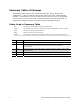
Summary Table of Changes The following table indicates the Specification Changes, Errata, Specification Clarifications, or Documentation Changes that apply to the Intel® Desktop Board DG45FC. Intel intends to fix some of the errata in a future revision of the desktop board, and to account for the other outstanding issues through documentation or specification changes as noted. This table uses the following notations: Codes Used in Summary Table Doc: Document change or update that will be implemented.
Specification Changes The Specification Changes listed in this section apply to the Intel® Desktop Board DG45FC Technical Product Specification (Order Number E35964). 1. The following Caution statement was modified in the Technical Product Specification in Section 2.6 Thermal Considerations: 2.6 Thermal Considerations CAUTION A chassis with a maximum internal ambient temperature of 38 oC at the processor fan inlet is a requirement.
It is important to note that the temperature measurement in the system BIOS is a value reported by embedded thermal sensors in the components and does not directly correspond to the Maximum Case Temperature. Intel® Quiet System Technology (Intel® QST) monitors the embedded thermal sensor for system fan speed control. The upper operating limit when monitoring this thermal sensor is Tcontrol. Table 30.
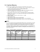
1.5 System Memory The board has two DIMM sockets and support the following memory features: • • • 1.8 V DDR2 SDRAM DIMMs with gold plated contacts, with the option to raise the voltage to support higher performance DDR2 SDRAM DIMMs Dual channel interleaved mode support Unbuffered, single-sided or double-sided DIMMs with the following restriction: Double-sided DIMMs with x16 organization are not supported.
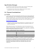
2.1.1 Addressable Memory The board utilizes 8 GB of addressable system memory. Typically the address space that is allocated for PCI Express configuration space, BIOS (SPI Flash), and chipset overhead resides above the top of DRAM (total system memory). On a system that has 8 GB of system memory installed, it is not possible to use all of the installed memory due to system address space being allocated for other system critical functions.
The amount of installed memory that can be used will vary based on add-in cards and BIOS settings and operating system installed. Figure 8 shows a schematic of the system memory map. All installed system memory can be used when there is no overlap of system addresses. Figure 8.
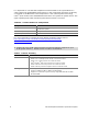
Table 10 lists the system memory map. Table 10. System Memory Map 12 Address Range (decimal) Address Range (hex) Size Description 1024 K - 8388608 K 100000 - 1FFFFFFFF 8191 MB Extended memory 960 K - 1024 K F0000 - FFFFF 64 KB Runtime BIOS 896 K - 960 K E0000 - EFFFF 64 KB Reserved 800 K - 896 K C8000 - DFFFF 96 KB Potential available high DOS memory (open to the PCI bus). Dependent on video adapter used.