
Intel Desktop Board DG45FC Product Guide


Intel Desktop Board DG45FC Product Guide
Serial Port Header
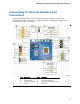
See Figure 17, E for the location of the serial port header. Table 10 shows the pin
assignments for the header.
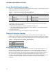
Table 10. Serial Port Header Signal Names
Pin Signal Name Pin Signal Name
1 DCD 2 RXD#
3 TXD# 4 DTR
5 Ground 6 DSR
7 RTS 8 CTS
9 RI 10 No Connection
Alternate Front Panel Power LED Header
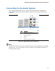
Figure 17, G shows the location of the alternate front panel power LED header. Pins 1
and 3 of this header duplicate the signals on pins 2 and 4 of the front panel header. If
your chassis has a three-pin power LED cable, connect it to this header. Table 11
shows the pin assignments for the alternate front panel header.
Table 11. Alternate Front Panel Power LED Header Signal Names
Pin Description In/Out
1 Front panel green LED Out
2 No pin
3 Front panel yellow LED Out
Front Panel Header
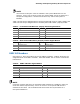
See Figure 17, H for the location of the multi-colored front panel header. Table 12
shows the pin assignments for the front panel header.
Table 12. Front Panel Header Signal Names
Pin Description In/Out
Pin Description In/Out
Hard Drive Activity LED Power LED
1 Hard disk LED pull-up to +5 V
Out 2 Front panel green LED Out
3 Hard disk active LED Out 4 Front panel yellow LED Out
Reset Switch On/Off Switch
5 Ground 6 Power switch In
7 Reset switch In 8 Ground
Power Not Connected
9 Power Out 10 No pin
44