
Intel Desktop Board DG45FC Product Guide

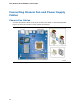


Installing and Replacing Desktop Board Components
NOTE
The Consumer IR option must be enabled in the system BIOS before it can
function. Press <F2> at boot to enter the system BIOS, and go to Advanced >
Peripheral Configuration > Enhanced Consumer IR, and set this option to
Enabled.
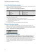
Table 7 shows the pin assignments for the front panel CIR receiver (input) header and
Table 8 shows the pin assignments for the back panel CIR emitter (output) header.
Table 7. Front Panel CIR Receiver (Input) Header Signal Names
Pin Signal Name Pin Signal Name
1 Ground 2 LED
3 No Connection 4 Learn-In
5 +5 V Standby 6 Vcc
7 Key (no pin) 8 CIR Input
Table 8. Back Panel CIR Emitter (Output) Header Signal Names
Pin Signal Name Pin Signal Name
1 Emitter Out 1 2 Emitter Out 2
3 Ground 4 Key (no pin)
5 Jack Detect 1 6 Jack Detect 2
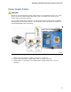
USB 2.0 Headers
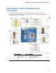
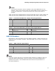
See Figure 17, D for the location of the two USB 2.0 headers. Table 9 shows the pin
assignments for each USB 2.0 header. Each USB header can be used to connect two
USB devices.
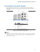
Table 9. USB 2.0 Header Signal Names
USB Port A USB Port B
Pin Signal Name Pin Signal Name
1 Power (+5 V) 2 Power (+5 V)
3 D- 4 D-
5 D+ 6 D+
7 Ground 8 Ground
9 Key 10 No Connection
Note: USB ports may be assigned as needed.
NOTE
Computer systems that have an unshielded cable attached to a USB port might not
meet FCC Class B requirements, even if no device or a low-speed USB device is
attached to the cable. Use a shielded cable that meets the requirements for a
full-speed USB device.
43