
Intel Desktop Board DG45FC Product Guide


Intel Desktop Board DG45FC Product Guide
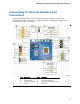
Front Panel HD Audio Header
Figure 17, A shows the location of the front panel audio header. Table 5 shows the pin
assignments for the front panel audio header.
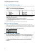
Table 5. Front Panel Audio Header Signal Names
Pin Signal Name Pin Signal Name
1 PORT 1L 2 GND
3 PORT 1R 4 PRESENCE#
5 PORT 2R 6 SENSE1_RETURN
7 SENSE_SEND 8 KEY (no pin)
9 PORT 2L 10 SENSE2_RETURN
To install the cable that connects your front panel audio solution to the front panel
audio header, follow these steps:
1. Observe the precautions in "Before You Begin" on page 27.
2. Turn off all peripheral devices connected to the computer. Turn off the computer
and disconnect the AC power cord.
3. Remove the cover.
4. Install a correctly keyed and shielded front panel audio cable.
Chassis Intrusion Header
Figure 17, B on page 41 shows the location of the chassis intrusion header. This
header can be connected to a mechanical switch on the chassis to detect if the chassis
cover is removed. Table 6 shows the pin assignments for the chassis intrusion header.
Table 6. Chassis Intrusion Header Signal Names
Pin Description
1 Intruder
2 Ground
Consumer IR (CIR) Headers
The Desktop Board has two CIR headers: the receiver or input header (Figure 17, F)
and the output or emitter header (Figure 17, C). The receiver header consists of a
filtered translated infrared input compliant with Microsoft CIR specifications and a
“learning” infrared input. The learning input is a high-pass input which the computer
can use to “learn” to speak the infrared communication language of other user
remotes. The emitter header consists of two output ports which the computer can use
to emulate “learned” infrared commands in order to control external electronic
hardware.
42