Intel® Desktop Board DG41MJ Product Guide Order Number: E59138-001
Revision History Revision -001 Revision History First release of the Intel® Desktop Board DG41MJ Product Guide Date February 2009 If an FCC declaration of conformity marking is present on the board, the following statement applies: FCC Declaration of Conformity This device complies with Part 15 of the FCC Rules.
Preface This Product Guide gives information about board layout, component installation, BIOS update, and regulatory requirements for Intel® Desktop Board DG41MJ. Intended Audience The Product Guide is intended for technically qualified personnel. It is not intended for general audiences. Use Only for Intended Applications All Intel Desktop Boards are evaluated as Information Technology Equipment (I.T.E.
Intel Desktop Board DG41MJ Product Guide Conventions The following conventions are used in this manual: CAUTION Cautions warn the user about how to prevent damage to hardware or loss of data. NOTE Notes call attention to important information. Terminology The table below gives descriptions of some common terms used in the product guide.
Contents 1 Desktop Board Features Desktop Board Components.................................................................................11 Processor..........................................................................................................12 Main Memory.....................................................................................................13 Intel® G41 Express Chipset .................................................................................14 Graphics Support..........
Intel Desktop Board DG41MJ Product Guide Connecting the Processor Fan Heat Sink Cable................................................31 Removing the Processor ..............................................................................31 Installing and Removing Memory..........................................................................32 Installing DIMMs ........................................................................................33 Removing DIMMs..........................................
Contents Figures 1. Intel Desktop Board DG41MJ Components ........................................................11 2. LAN Connector LEDs ......................................................................................16 3. Location of the Standby Power Indicator ...........................................................21 4. Installing the I/O Shield .................................................................................25 5. Intel Desktop Board DG41MJ Mounting Screw Hole Locations......
Intel Desktop Board DG41MJ Product Guide viii
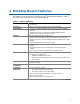
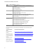
1 Desktop Board Features This chapter briefly describes the features of Intel® Desktop Board DG41MJ. Table 1 summarizes the major features of the Desktop Board. Table 1. Feature Summary Form Factor Mini-ITX (170.18 millimeters [6.70 inches] x 170.18 millimeters [6.
Intel Desktop Board DG41MJ Product Guide Table 1.
Desktop Board Features Desktop Board Components Figure 1 shows the approximate location of the major components on Intel Desktop Board DG41MJ. Figure 1.
Intel Desktop Board DG41MJ Product Guide Table 2. Intel Desktop Board DG41MJ Components Label Description A Front panel audio header B Back panel connectors C 12 V processor core voltage connector (2 x 2 pin) D High-speed USB 2.
Desktop Board Features Main Memory NOTE To be fully compliant with all applicable Intel ® SDRAM memory specifications, the board should be populated with DIMMs that support the Serial Presence Detect (SPD) data structure. If your memory modules do not support SPD, you will see a notification to this effect on the screen at power up. The BIOS will attempt to configure the memory controller for normal operation.
Intel Desktop Board DG41MJ Product Guide Intel® G41 Express Chipset The Intel G41 Express Chipset consists of the following devices: • • Intel G41 Express Chipset Graphics and Memory Controller Hub (GMCH) with Direct Media Interface (DMI) Intel 82801GB I/O Controller Hub (ICH7) with DMI The GMCH component provides interfaces to the processor, memory, PCI, and the DMI interconnect. The component also provides integrated graphics capabilities supporting 3D, 2D, and display capabilities.
Desktop Board Features Audio Subsystem The onboard audio subsystem consists of the following: • • • • Intel® ICH7 Realtek ALC888VC audio codec Back panel audio connectors (see Figure 19) Front panel audio header supporting both Intel High Definition Audio and AC ’97 Audio (see Figure 18, A) The audio subsystem supports the following features: • • A signal-to-noise (S/N) ratio of 95 dB Independent 5.
Intel Desktop Board DG41MJ Product Guide LAN Subsystem The LAN subsystem includes: • • • Intel ICH7 Realtek 8111D-GR Gigabit Ethernet Controller for operation at 10/100/1000 Mb/s RJ-45 LAN connector with integrated status LEDs The subsystem features: • CSMA/CD protocol engine • LAN connect interface between ICH7 and the LAN controller • PCI bus power management Two LEDs are built into the RJ-45 LAN connector located on the back panel (see Figure 2). These LEDs indicate the status of the LAN. Figure 2.
Desktop Board Features USB 2.0 Support The Desktop Board supports up to eight USB 2.0 ports (four ports routed to the back panel and four ports routed to two internal headers) via ICH7. USB 2.0 ports are backward compatible with USB 1.1 devices. USB 1.1 devices will function normally at USB 1.1 speeds. USB 2.0 support requires both an operating system and drivers that fully support USB 2.0 transfer rates. Disabling Hi-Speed USB in the BIOS reverts all USB 2.0 ports to USB 1.1 operation.
Intel Desktop Board DG41MJ Product Guide Security Passwords The BIOS includes security features that restrict whether the BIOS Setup program can be accessed and who can boot the computer. A supervisor password and a user password can be set for the BIOS Setup and for booting the computer, with the following restrictions: • • • The supervisor password gives unrestricted access to view and change all Setup options.
Desktop Board Features Power Management Features Power management is implemented at several levels, including: • • • Software support through the Advanced Configuration and Power Interface (ACPI) Hardware support: ⎯ Power connectors ⎯ Fan headers ⎯ LAN wake capabilities ⎯ Instantly Available PC technology (Suspend to RAM) ⎯ +5 V standby power indicator LED ⎯ Wake from USB ⎯ Power Management Event signal (PME#) wake-up support ⎯ Wake from PS/2 devices ⎯ Wake from serial port ENERGY STAR capable ACPI ACPI
Intel Desktop Board DG41MJ Product Guide Fan Headers The function/operation of the fans is as follows: • • • • • The fans are on when the computer is in the ACPI S0 state. The fans are off when the computer is in the ACPI S3, S4, or S5 state. The processor fan header is wired to a fan tachometer input. The chassis fan header has an independent tachometer input to the hardware monitoring and fan control device.
Desktop Board Features The Desktop Board supports the PCI Bus Power Management Interface Specification. Add-in cards that support this specification can participate in power management and can be used to wake the computer. +5 V Standby Power Indicator LED CAUTION If the AC power has been switched off and the standby power indicator is still lit, disconnect the power cord before installing or removing any devices connected to the board. Failure to do so could damage the board and any attached devices.
Intel Desktop Board DG41MJ Product Guide Wake from USB Support NOTE Wake from USB requires the use of a USB peripheral that supports Wake from USB. USB bus activity wakes the computer from an ACPI S1 or S3 state. PME# Signal Wake-up Support When the PME# signal on the PCI bus is asserted, the computer wakes from an ACPI S1, S3, S4, or S5 (LAN only) state. Wake From PS/2 Devices PS/2 device activity wakes the computer from an ACPI S1 or S3 state.
2 Installing and Replacing Desktop Board Components This chapter tells you how to: • • • • • • • • • • • Install the I/O shield Install and remove the Desktop Board Install and remove a processor Install and remove memory Use the Serial ATA cables Connect to the internal headers and connectors Connect to the audio system Connect chassis fan and power supply cables Set the BIOS configuration jumper Clear passwords Replace the battery Before You Begin CAUTION The procedures in this chapter assume familiarit
Intel Desktop Board DG41MJ Product Guide Installation Precautions When you install and test the Intel Desktop Board, observe all warnings and cautions in the installation instructions.
Installing and Replacing Desktop Board Components Installing the I/O Shield The Desktop Board comes with an I/O shield. When installed in the chassis, the shield blocks radio frequency transmissions, protects internal components from dust and foreign objects, and promotes correct airflow within the chassis. Install the I/O shield before installing the Desktop Board in the chassis. Place the shield inside the chassis as shown in Figure 4. Press the shield into place so that it fits tightly and securely.
Intel Desktop Board DG41MJ Product Guide Installing and Removing the Desktop Board CAUTION Only qualified technical personnel should do this procedure. Disconnect the computer from its power source before performing the procedures described here. Failure to disconnect the power before you open the computer can result in personal injury or equipment damage. Refer to your chassis manual for instructions on installing and removing the Desktop Board.
Installing and Replacing Desktop Board Components Installing and Removing a Processor Instructions on how to install the processor to the Desktop Board are given below. Installing a Processor CAUTION Before installing or removing the processor, make sure the AC power has been removed by unplugging the power cord from the computer; the standby power LED should not be lit (see Figure 3 on page 21). Failure to do so could damage the processor and the board.
Intel Desktop Board DG41MJ Product Guide 3. Lift the load plate (Figure 7, A). Do not touch the socket contacts (Figure 7, B). Figure 7. Lift the Load Plate 4. Remove the plastic protective socket cover from the load plate (Figure 8). Do not discard the protective socket cover. Always replace the socket cover if the processor is removed from the socket. Figure 8.
Installing and Replacing Desktop Board Components 5. Remove the processor from the protective processor cover. Hold the processor only at the edges, being careful not to touch the bottom of the processor (Figure 9). Do not discard the protective processor cover. Always replace the processor cover if the processor is removed from the socket. Figure 9. Remove the Processor from the Protective Processor Cover 6. Hold the processor with your thumb and index fingers oriented as shown in Figure 10.
Intel Desktop Board DG41MJ Product Guide 7. Pressing down on the load plate (Figure 11, A), close and engage the socket lever (Figure 11, B). Figure 11.
Installing and Replacing Desktop Board Components Installing the Processor Fan Heat Sink Intel Desktop Board DG41MJ has mounting holes for a processor fan heat sink. For instructions on how to attach the processor fan heat sink to the Desktop Board, refer to the boxed processor manual. Connecting the Processor Fan Heat Sink Cable Connect the processor fan heat sink cable to the 4-pin processor fan header (see Figure 12).
Intel Desktop Board DG41MJ Product Guide Installing and Removing Memory NOTE To be fully compliant with all applicable Intel SDRAM memory specifications, the board requires DIMMs that support the Serial Presence Detect (SPD) data structure. The Desktop Board has two 240-pin DDR2 DIMM sockets providing Channel A and Channel B. For optimum dual-channel performance, install a matched pair of DIMMs equal in speed and size (see Figure 13). Figure 13.
Installing and Replacing Desktop Board Components Installing DIMMs To make sure you have the correct DIMM, place it on the illustration of the DDR2 DIMM in Figure 14. All the notches should match with the DDR2 DIMM. Figure 14.
Intel Desktop Board DG41MJ Product Guide To install a DIMM, follow these steps: 1. Observe the precautions in "Before You Begin" on page 23. 2. Turn off all peripheral devices connected to the computer. Turn off the computer and disconnect the AC power cord. 3. Remove the computer’s cover and locate the DIMM sockets (see Figure 15). Figure 15. Installing a DIMM 4. Make sure the clips at either end of the DIMM socket(s) are pushed outward to the open position. 5.
Installing and Replacing Desktop Board Components Removing DIMMs To remove a DIMM, follow these steps: 1. 2. 3. 4. 5. Observe the precautions in "Before You Begin" on page 23. Turn off all peripheral devices connected to the computer. Turn off the computer. Remove the AC power cord from the computer. Remove the computer’s cover. Gently spread the retaining clips at each end of the DIMM socket. The DIMM pops out of the socket. 6.
Intel Desktop Board DG41MJ Product Guide Connecting a Standard SATA Drive You can use the standard SATA data cable supplied to connect a standard SATA drive to the Desktop Board. For correct cable function: 1. Observe the precautions in “Before You Begin” on page 23. 2. Attach one end of the SATA data cable to one of the SATA connectors on the board (Figure 16, A) and attach the other end of the cable to the SATA drive (Figure 16, B). Figure 16.
Installing and Replacing Desktop Board Components Connecting a Slimline SATA Drive You can use the SATA-to-Slimline SATA adapter cable to connect a slimline SATA drive to a standard SATA data connector on the Desktop Board. This adapter splits a Slimline SATA connector into a standard SATA data cable and a power connector which plugs into a 4-pin 5 V Molex* power connector from an ATX12V power supply. For correct adapter cable function: 1. Observe the precautions in “Before You Begin” on page 23. 2.
Intel Desktop Board DG41MJ Product Guide Connecting to the Internal Headers and Connectors Before connecting cables to the internal headers and connectors, observe the precautions in “Before You Begin” on page 23. Figure 18 shows the location of the internal headers and connectors for Intel Desktop Board DG41MJ. Figure 18.
Installing and Replacing Desktop Board Components Front Panel Audio Header The front panel audio header shown in Figure 18, A on page 38 supports both Intel HD Audio and AC’97 Audio. Table 5 shows the pin assignments and signal names for Intel HD Audio and Table 6 shows the pin assignments and signal names for AC’97 Audio. Table 5.
Intel Desktop Board DG41MJ Product Guide USB 2.0 Headers Before connecting to the USB 2.0 headers, observe the precautions in "Before You Begin" on page 23. See Figure 18, C on page 38 for the location of the USB 2.0 headers. Table 8 shows the pin assignments for each USB 2.0 header. Each USB header can be used to connect two USB devices. Table 8. USB 2.
Installing and Replacing Desktop Board Components Alternate Front Panel Power LED Header Figure 18, E on page 38 shows the location of the alternate front panel power LED header. Pins 1 and 3 of this header duplicate the signals on pins 2 and 4 of the front panel header. If your chassis has a three-pin power LED cable, connect it to this header. Table 10 shows the pin assignments for the alternate front panel power LED header. Table 10.
Intel Desktop Board DG41MJ Product Guide Connecting to the Back Panel Audio Connectors After the audio driver has been installed, the multi-channel audio feature can be enabled. Figure 19 shows the back panel audio connectors. The default connector assignments are shown in the figure. Refer to Table 3 on page 15 for audio connector retasking information. Item Description A Line In B Line Out C Mic In Figure 19.
Installing and Replacing Desktop Board Components Connecting Chassis Fan and Power Supply Cables Connecting a Chassis Fan Cable Connect your chassis fan cable to the 3-pin chassis fan header on the Desktop Board. Figure 20 shows the location of the chassis fan header. Figure 20.
Intel Desktop Board DG41MJ Product Guide Connecting Supply Power Cables CAUTION Failure to use an appropriate power supply and/or not connecting the 12 V (2 x 2 pin) power connector to the Desktop Board may result in damage to the board or the system may not function properly. The 2 x 12 pin main power connector on the Desktop Board is backwards compatible with ATX12V power supplies with 2 x 10 connectors. Figure 21 shows the location of the Desktop Board power connectors. Figure 21.
Installing and Replacing Desktop Board Components Setting the BIOS Configuration Jumper NOTE Always turn off the power and unplug the power cord from the computer before moving the jumper. Moving the jumper with the power on may result in unreliable computer operation. Figure 22 shows the location of the Desktop Board’s BIOS configuration jumper block. Figure 22.
Intel Desktop Board DG41MJ Product Guide Table 12. Jumper Settings for the BIOS Setup Program Modes Jumper Setting Mode Description Normal (default) (1-2) The BIOS uses the current configuration and passwords for booting. Configure (2-3) After the Power-On Self-Test (POST) runs, the BIOS displays the Maintenance Menu. Use this menu to clear passwords. Recovery (None) The BIOS recovers data in the event of a failed BIOS update.
Installing and Replacing Desktop Board Components 12. To restore normal operation, place the jumper on pins 1-2 as shown below. 13. Replace the cover, plug in the computer, and turn on the computer. Replacing the Battery A coin-cell battery (CR2032) powers the real-time clock and CMOS memory. When the computer is not plugged into a wall socket, the battery has an estimated life of three years. When the computer is plugged in, the standby current from the power supply extends the life of the battery.
Intel Desktop Board DG41MJ Product Guide VARO Räjähdysvaara, jos pariston tyyppi on väärä. Paristot on kierrätettävä, jos se on mahdollista. Käytetyt paristot on hävitettävä paikallisten ympäristömääräysten mukaisesti. VORSICHT Bei falschem Einsetzen einer neuen Batterie besteht Explosionsgefahr. Die Batterie darf nur durch denselben oder einen entsprechenden, vom Hersteller empfohlenen Batterietyp ersetzt werden. Entsorgen Sie verbrauchte Batterien den Anweisungen des Herstellers entsprechend.
Installing and Replacing Desktop Board Components Προσοχή Υπάρχει κίνδυνος για έκρηξη σε περίπτωση που η μπαταρία αντικατασταθεί από μία λανθασμένου τύπου. Οι μπαταρίες θα πρέπει να ανακυκλώνονται όταν κάτι τέτοιο είναι δυνατό. Η απόρριψη των χρησιμοποιημένων μπαταριών πρέπει να γίνεται σύμφωνα με τους κατά τόπο περιβαλλοντικούς κανονισμούς. VIGYÁZAT Ha a telepet nem a megfelelő típusú telepre cseréli, az felrobbanhat. A telepeket lehetőség szerint újra kell hasznosítani.
Intel Desktop Board DG41MJ Product Guide POZOR Zamenjava baterije z baterijo drugačnega tipa lahko povzroči eksplozijo. Če je mogoče, baterije reciklirajte. Rabljene baterije zavrzite v skladu z lokalnimi okoljevarstvenimi predpisi. . UYARI Yanlış türde pil takıldığında patlama riski vardır. Piller mümkün olduğunda geri dönüştürülmelidir. Kullanılmış piller, yerel çevre yasalarına uygun olarak atılmalıdır. OСТОРОГА Використовуйте батареї правильного типу, інакше існуватиме ризик вибуху.
Installing and Replacing Desktop Board Components To replace the battery, follow these steps: 1. Observe the precautions in "Before You Begin" (see page 23). 2. Turn off all peripheral devices connected to the computer. Disconnect the computer’s power cord from the AC power source (wall outlet or power adapter). 3. Remove the computer cover. 4. Locate the battery on the board (see Figure 23). 5. Push the battery retention clip aside and remove the battery from the connector as shown in Figure 23.
Intel Desktop Board DG41MJ Product Guide 52
3 Updating the BIOS The BIOS Setup program can be used to view and change the BIOS settings for the computer. You can access the BIOS Setup program by pressing the key after the Power-On Self-Test (POST) memory test begins and before the operating system boot begins. This chapter tells you how to update the BIOS by either using the Intel Express BIOS Update utility or the Iflash Memory Update utility, and how to recover the BIOS if an update fails.
Intel Desktop Board DG41MJ Product Guide Updating the BIOS with the ISO Image BIOS Update File or the Iflash Memory Update Utility You can use the information in this section to update the BIOS using either the Iflash Memory Update Utility or the ISO Image BIOS update file. Obtaining the BIOS Update File You can update to a new version of the BIOS by using the ISO Image BIOS update file (recommended), or Iflash BIOS update file.
Updating the BIOS Follow these instructions to upgrade the BIOS using the ISO Image BIOS file: 1. Download the ISO Image BIOS file. 2. Using software capable of uncompressing and writing an ISO image file to CD, burn the data to a blank CD. NOTE Copying the ISO Image BIOS file to CD will not work. The completed CD should contain multiple files and a directory. 3. Insert the CD that was created in the CD-ROM drive of the computer to be upgraded and boot the system. 4.
Intel Desktop Board DG41MJ Product Guide 1. Uncompress the BIOS update file and copy the .BIO file, IFLASH.EXE, and .ITK file (optional) to a bootable USB flash drive or other bootable USB media. 2. Configure the BIOS or use the F10 option during POST to boot to the USB device. 3. Manually run the IFLASH.EXE file from the USB device and manually update the BIOS. Recovering the BIOS It is unlikely that anything will interrupt the BIOS update; however, if an interruption occurs, the BIOS could be damaged.
A Error Messages and Indicators Intel Desktop Board DG41MJ reports POST errors in two ways: • • By sounding a beep code By displaying an error message on the monitor BIOS Beep Codes The BIOS also issues a beep code (one long tone followed by two short tones) during POST if the video configuration fails (a faulty video card or no card installed) or if an external ROM module does not properly checksum to zero. Table 13 lists the BIOS codes. Table 13.
Intel Desktop Board DG41MJ Product Guide 58
B Regulatory Compliance This appendix contains the following regulatory compliance information for Intel Desktop Board DG41MJ: • • • • • Safety standards European Union Declaration of Conformity statement Product Ecology statements Electromagnetic Compatibility (EMC) regulations Product certifications Safety Standards Intel Desktop Board DG41MJ complies with the safety standards stated in Table 15 when correctly installed in a compatible host system. Table 15.
Intel Desktop Board DG41MJ Product Guide European Union Declaration of Conformity Statement We, Intel Corporation, declare under our sole responsibility that the product Intel® Desktop Board DG41MJ is in conformity with all applicable essential requirements necessary for CE marking, following the provisions of the European Council Directives 2004/108/EC (EMC Directive) and 2006/95/EC (Low Voltage Directive).
Regulatory Compliance Lietuvių Šis produktas atitinka Europos direktyvų 2004/108/EC ir 2006/95/EC nuostatas. Malti Dan il-prodott hu konformi mal-provvedimenti tad-Direttivi Ewropej 2004/108/EC u 2006/95/EC. Norsk Dette produktet er i henhold til bestemmelsene i det europeiske direktivet 2004/108/EC & 2006/95/EC. Polski Niniejszy produkt jest zgodny z postanowieniami Dyrektyw Unii Europejskiej 2004/108/EC i 2006/95/EC.
Intel Desktop Board DG41MJ Product Guide Deutsch Als Teil von Intels Engagement für den Umweltschutz hat das Unternehmen das Intel Produkt-Recyclingprogramm implementiert, das Einzelhandelskunden von Intel Markenprodukten ermöglicht, gebrauchte Produkte an ausgewählte Standorte für ordnungsgemäßes Recycling zurückzugeben. Details zu diesem Programm, einschließlich der darin eingeschlossenen Produkte, verfügbaren Standorte, Versandanweisungen, Bedingungen usw., finden Sie auf der http://www.intel.
Regulatory Compliance Portuguese Como parte deste compromisso com o respeito ao ambiente, a Intel implementou o Programa de Reciclagem de Produtos para que os consumidores finais possam enviar produtos Intel usados para locais selecionados, onde esses produtos são reciclados de maneira adequada. Consulte o site http://www.intel.
Intel Desktop Board DG41MJ Product Guide Table 16 shows the lead-free board markings as they appear on the board and accompanying collateral. Table 16. Lead-Free Board Markings Description Mark nd Lead-Free 2 Level Interconnect: This symbol is used to identify electrical and electronic assemblies and components in which the lead (Pb) concentration level in the Intel Desktop Board substrate and the solder connections from the board to the components (second-level interconnect) is not greater than 0.
Regulatory Compliance EMC Regulations Intel Desktop Board DG41MJ complies with the EMC regulations stated in Table 17 when correctly installed in a compatible host system. Table 17. EMC Regulations Regulation Title FCC 47 CFR Part 15, Subpart B Title 47 of the Code of Federal Regulations, Part 15, Subpart B, Radio Frequency Devices. (USA) ICES-003 Issue 4 (Class B) Interference-Causing Equipment Standard, Digital Apparatus.
Intel Desktop Board DG41MJ Product Guide Korean Class B statement translation: This is household equipment that is certified to comply with EMC requirements. You may use this equipment in residential environments and other non-residential environments. Ensure Electromagnetic Compatibility (EMC) Compliance Before computer integration, make sure that the power supply and other modules or peripherals, as applicable, have passed Class B EMC testing and are marked accordingly.
Regulatory Compliance Product Certifications Board-Level Certification Markings Intel Desktop Board DG41MJ has the product certification markings shown in Table 18. Table 18. Product Certification Markings Description Mark UL joint US/Canada Recognized Component mark. Includes adjacent UL file number for Intel Desktop Boards: E210882. FCC Declaration of Conformity logo mark for Class B equipment. Includes Intel name and DG41MJ model designation. CE mark.
Intel Desktop Board DG41MJ Product Guide Chassis and Component Certifications Ensure that the chassis and certain components; such as the power supply, peripheral drives, wiring, and cables; are components certified for the country or market where used. Agency certification marks on the product are proof of certification. Typical product certifications include: In Europe The CE marking signifies compliance with all applicable European requirements.