Intel® Desktop Board DG33TL Product Guide Order Number: D90031-003
Revision History Revision -001 -002 -003 Revision History First release of the Intel® Desktop Board DG33TL Product Guide Second release of the Intel® Desktop Board DG33TL Product Guide Third release of the Intel® Desktop Board DG33TL Product Guide Date April 2007 May 2007 January 2008 If an FCC declaration of conformity marking is present on the board, the following statement applies: FCC Declaration of Conformity This device complies with Part 15 of the FCC Rules.
Preface This Product Guide gives information about board layout, component installation, BIOS update, and regulatory requirements for Intel® Desktop Board DG33TL. Intended Audience The Product Guide is intended for technically qualified personnel. It is not intended for general audiences. Use Only for Intended Applications All Intel Desktop Boards are evaluated as Information Technology Equipment (I.T.E.
Intel Desktop Board DG33TL Product Guide Conventions The following conventions are used in this manual: CAUTION Cautions warn the user about how to prevent damage to hardware or loss of data. NOTE Notes call attention to important information. Terminology The table below gives descriptions of some common terms used in the product guide.
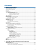
Contents 1 Desktop Board Features Supported Operating Systems..............................................................................10 Desktop Board Components.................................................................................11 Processor..........................................................................................................13 Main Memory.....................................................................................................13 Intel® G33 Express Chipset ..
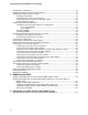
Intel Desktop Board DG33TL Product Guide Installing the I/O Shield ......................................................................................29 Installing and Removing the Desktop Board ...........................................................30 Installing and Removing a Processor .....................................................................31 Installing a Processor ..................................................................................
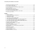
Contents 5 Configuring for RAID (Intel® Matrix Storage Technology) Configuring the BIOS for Intel Matrix Storage Technology ........................................71 Creating Your RAID Set.......................................................................................71 Loading the Intel Matrix Storage Technology RAID Drivers and Software....................72 Setting Up a “RAID Ready” System.......................................................................
Intel Desktop Board DG33TL Product Guide 19. 20. 21. 22. 23. 24. 25. 26. 27. 28. Removing a PCI Express x16 Card ..................................................................43 Connecting the IDE Cable ..............................................................................45 Connecting a Serial ATA Cable........................................................................46 Connecting the External Serial ATA Adapter Bracket ..........................................47 Internal Headers .....
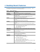
1 Desktop Board Features This chapter briefly describes the features of Intel® Desktop Board DG33TL. Table 1 summarizes the major features of the Desktop Board. Table 1. Feature Summary Form Factor microATX (243.84 millimeters [9.60 inches] x 243.84 millimeters [9.60 inches]) Processor Support for an Intel® processor in the LGA775 package Main Memory • Four 240-pin, DDR2 1.
Intel Desktop Board DG33TL Product Guide Table 1.
Desktop Board Features Desktop Board Components Figure 1 shows the approximate location of the major components on Desktop Board DG33TL. Figure 1.
Intel Desktop Board DG33TL Product Guide Table 2.
Desktop Board Features Related Links: Go to the following links for more information about: • Desktop Board DG33TL http://www.intel.com/design/motherbd http://support.intel.com/support/motherboards/desktop • • • Supported processors Audio software and utilities LAN software and drivers http://www.intel.com/go/findCPU http://www.intel.com/design/motherbd http://www.intel.
Intel Desktop Board DG33TL Product Guide • Support for: ⎯ Unbuffered, non-registered single or double-sided DIMMs ⎯ Non-ECC DDR2 memory ⎯ DIMM Type and Timings listed below: Type DDR2-800 DDR2-667 Timing 5-5-5 or 6-6-6 only 5-5-5 only ⎯ Serial Presence Detect (SPD) memory only ⎯ Memory configurations listed below: • Up to 2.0 GB utilizing 256 Mb technology • Up to 4.0 GB utilizing 512 Mb or 1 Gb technology • Up to 8.
Desktop Board Features Intel G33 Graphics Subsystem The Intel G33 Express Chipset contains two separate, mutually exclusive graphics options. Either the integrated Intel Graphics Media Accelerator 3100 (Intel® GMA 3100) graphics controller is used or a PCI Express x16 add-in card can be used. When a PCI Express x16 add-in card is installed, the Intel GMA 3100 graphics controller is disabled.
Intel Desktop Board DG33TL Product Guide Digital Video Interface (DVI) The DVI port supports only DVI-D (digital only) displays. The maximum support resolution is 1600 x 1200 at a 60 Hz refresh rate. The DVI port is compliant with the DVI 1.0 specification. Depending on the type of add-in card installed in the PCI Express x16 connector, the DVI and VGA ports will behave as described in Table 3. Table 3.
Desktop Board Features Legacy Input/Output (I/O) Controller The I/O controller features the following: • • • • • • Consumer Infrared (CIR) support Low pin count (LPC) interface One serial port interface via an onboard header Serial IRQ interface compatible with serialized IRQ support for PCI systems Intelligent power management, including a programmable wake up event interface PCI power management support LAN Subsystem The LAN subsystem includes: • • • Intel ICH9R Intel 82566DC Gigabit (10/100/1000 Mb/s
Intel Desktop Board DG33TL Product Guide Table 4 describes the LED states when the board is powered up and the LAN subsystem is operating. Table 4. LAN Connector LEDs LED LED Color LED State Indicates A Green Off LAN link is not established On LAN link is established B Blinking LAN activity is occurring N/A Off 10 Mb/s data rate Green On 100 Mb/s data rate Yellow On 1000 Mb/s data rate Hi-Speed USB 2.0 Support The Desktop Board supports up to 12 USB 2.
Desktop Board Features Serial ATA RAID The ICH9R supports the following RAID (Redundant Array of Independent Drives) levels: • • • • RAID RAID RAID RAID 0 - data striping 1 - data mirroring 0+1 (or RAID 10) - data striping and mirroring 5 - distributed parity For information on configuring your system for RAID using Intel® Matrix Storage Technology see Chapter 4.
Intel Desktop Board DG33TL Product Guide Serial ATA or IDE device. You can override the auto-configuration options by specifying manual configuration in the BIOS Setup program. PCI and PCI Express* Auto Configuration If you install a PCI/PCI Express add-in card in your computer, the PCI/PCI Express auto-configuration utility in the BIOS automatically detects and configures the resources (IRQs, DMA channels, and I/O space) for that add-in card.
Desktop Board Features Hardware Monitoring and Fan Speed Control The features of the hardware monitoring and fan speed control include: • • Monitoring of power supply voltages to detect levels above and below acceptable values Intel Quiet System Technology fan speed control, delivering acoustically-optimized thermal management NOTE • • Memory must be installed in the Channel A, DIMM 0 socket to enable Intel Quiet System Technology.
Intel Desktop Board DG33TL Product Guide ACPI ACPI gives the operating system direct control over the power management and Plug and Play functions of a computer. The use of ACPI with the Desktop Board requires an operating system that provides full ACPI support. Hardware Support Power Connectors ATX12V-compliant power supplies can turn off the computer power through system control. When an ACPI-enabled computer receives the correct command, the power supply removes all non-standby voltages.
Desktop Board Features Instantly Available PC Technology CAUTIONS For Instantly Available PC technology, the 5 V standby line for the power supply must be capable of delivering adequate +5 V standby current. Failure to provide adequate standby current when using this feature can damage the power supply and/or effect ACPI S3 sleep state functionality.
Intel Desktop Board DG33TL Product Guide Figure 3. Location of the Standby Power Indicator Related Links: For more information on standby current requirements for the Desktop Board, refer to the Technical Product Specification by going to the following link, finding the product, and selecting Product Documentation from the left-hand menu: http://support.intel.com/support/motherboards/desktop/ Wake from USB NOTE Wake from USB requires the use of a USB peripheral that supports Wake from USB.
Desktop Board Features ENERGY STAR* Capable In 2007, the US Department of Energy and the US Environmental Protection Agency revised the ENERGY STAR requirements. Intel worked directly with these two governmental agencies to define the new requirements. Currently Intel Desktop Boards are capable of meeting the new ENERGY STAR requirements depending upon system configuration. Go to the following link for information and recommendations concerning the the new ENERGY STAR requirements: http://www.intel.
Intel Desktop Board DG33TL Product Guide 26
2 Installing and Replacing Desktop Board Components This chapter tells you how to: • • • • • • • • • • • • • Install the I/O shield Install and remove the Desktop Board Install and remove a processor Install and remove memory Install and remove a PCI Express x16 card Connect the IDE and Serial ATA cables Install the External SATA (eSATA) adapter bracket Connect to the internal headers Connect to the flexible audio system Connect chassis fan and power supply cables Set the BIOS configuration jumper Clear pa
Intel Desktop Board DG33TL Product Guide Installation Precautions When you install and test the Intel Desktop Board, observe all warnings and cautions in the installation instructions.
Installing and Replacing Desktop Board Components Installing the I/O Shield The Desktop Board comes with an I/O shield. When installed in the chassis, the shield blocks radio frequency transmissions, protects internal components from dust and foreign objects, and promotes correct airflow within the chassis. Install the I/O shield before installing the Desktop Board in the chassis. Place the shield inside the chassis as shown in Figure 4. Press the shield into place so that it fits tightly and securely.
Intel Desktop Board DG33TL Product Guide Installing and Removing the Desktop Board CAUTION Only qualified technical personnel should do this procedure. Disconnect the computer from its power source before performing the procedures described here. Failure to disconnect the power before you open the computer can result in personal injury or equipment damage. Refer to your chassis manual for instructions on installing and removing the Desktop Board.
Installing and Replacing Desktop Board Components Installing and Removing a Processor Instructions on how to install the processor to the Desktop Board are given below. Installing a Processor CAUTION Before installing or removing the processor, make sure the AC power has been removed by unplugging the power cord from the computer; the standby power LED should not be lit (see Figure 3 on page 24). Failure to do so could damage the processor and the board.
Intel Desktop Board DG33TL Product Guide 3. Lift the load plate (Figure 7, A). Do not touch the socket contacts (Figure 7, B). Figure 7. Lift the Load Plate 4. Remove the plastic protective socket cover from the load plate (Figure 8). Do not discard the protective socket cover. Always replace the socket cover if the processor is removed from the socket. Figure 8.
Installing and Replacing Desktop Board Components 5. Remove the processor from the protective processor cover. Hold the processor only at the edges, being careful not to touch the bottom of the processor (see Figure 9). Do not discard the protective processor cover. Always replace the processor cover if the processor is removed from the socket. Figure 9. Remove the Processor from the Protective Processor Cover 6. Hold the processor with your thumb and index fingers oriented as shown in Figure 10.
Intel Desktop Board DG33TL Product Guide 7. Pressing down on the load plate (Figure 11, A), close and engage the socket lever (Figure 11, B). Figure 11. Close the Load Plate Installing the Processor Fan Heat Sink Desktop Board DG33TL has mounting holes for a processor fan heat sink. For instructions on how to attach the processor fan heat sink to the Desktop Board, refer to the boxed processor manual.
Installing and Replacing Desktop Board Components Connecting the Processor Fan Heat Sink Cable Connect the processor fan heat sink cable to the 4-pin processor fan header (see Figure 12). A fan with a 4-pin connector as shown in Figure 12, A is recommended; however, a fan with a 3-pin connector (Figure 12, B) can be used. However, since the fan with a 3-pin connector cannot use the onboard fan control, the fan will always operate at full speed. Figure 12.
Intel Desktop Board DG33TL Product Guide Removing the Processor For instructions on how to remove the processor fan heat sink and processor, refer to the processor installation manual. Installing and Removing Memory NOTE To be fully compliant with all applicable Intel SDRAM memory specifications, the board requires DIMMs that support the Serial Presence Detect (SPD) data structure. Desktop board DG33TL has four 240-pin DDR2 DIMM sockets arranged as DIMM 0 and DIMM 1 in both Channel A and Channel B.
Installing and Replacing Desktop Board Components Guidelines for Dual Channel Memory Configuration Before installing DIMMs, read and follow these guidelines for dual channel configuration. Two or Four DIMMs Install a matched pair of DIMMs equal in speed and size (see Figure 13) in DIMM 0 (blue) of channels A and B. Figure 13. Dual Channel Memory Configuration with Two DIMMs If additional memory is to be used, install another matched pair of DIMMs in DIMM 1 (black) in channels A and B (see Figure 14).
Intel Desktop Board DG33TL Product Guide Three DIMMs If you want to use three DIMMs in a dual-channel configuration, install a matched pair of DIMMs equal in speed and size in DIMM 0 (blue) and DIMM 1 (black) of channel A. Install a DIMM equal in speed and total size of the DIMMs installed in channel A in either DIMM 0 or DIMM 1 of channel B (see Figure 15). Figure 15. Dual Channel Memory Configuration with Three DIMMs NOTE All other memory configurations will result in single channel memory operation.
Installing and Replacing Desktop Board Components Installing DIMMs To make sure you have the correct DIMM, place it on the illustration of the DDR2 DIMM in Figure 16. All the notches should match with the DDR2 DIMM. Figure 16.
Intel Desktop Board DG33TL Product Guide NOTE Memory must be installed in the Channel A, DIMM 0 socket to enable Intel Quiet System Technology. To install a DIMM, follow these steps: 1. Observe the precautions in "Before You Begin" on page 27. 2. Turn off all peripheral devices connected to the computer. Turn off the computer and disconnect the AC power cord. 3. Remove the computer’s cover and locate the DIMM sockets (see Figure 17). Figure 17. Installing a DIMM 4.
Installing and Replacing Desktop Board Components 7. Insert the bottom edge of the DIMM into the socket. 8. When the DIMM is inserted, push down on the top edge of the DIMM until the retaining clips snap into place. Make sure the clips are firmly in place. 9. Replace the computer’s cover and reconnect the AC power cord. Removing DIMMs To remove a DIMM, follow these steps: 1. 2. 3. 4. 5. Observe the precautions in "Before You Begin" on page 27. Turn off all peripheral devices connected to the computer.
Intel Desktop Board DG33TL Product Guide Installing and Removing a PCI Express x16 Card CAUTION When installing a PCI Express x16 card on the Desktop Board, ensure that the card is fully seated in the PCI Express x16 connector before you power on the system. If the card is not fully seated in the PCI Express connector, an electrical short may result across the PCI Express connector pins.
Installing and Replacing Desktop Board Components Removing the PCI Express x16 Card Follow these instructions to remove the PCI Express x16 card from the connector: 1. Observe the precautions in "Before You Begin" on page 27. 2. Remove the screw (Figure 19, A) that secures the card’s metal bracket to the chassis back panel. 3. Push the card ejector lever down using the tip of a pencil or similar tool (Figure 19, B) in the notch. This will release the card from the connector (C). 4.
Intel Desktop Board DG33TL Product Guide Connecting the IDE Cable The IDE cable can be used to connect two IDE drives to the Desktop Board. The cable supports the ATA-66/100 transfer protocol. Figure 20 shows the correct installation of the cable. NOTES ATA-66/100 compatible cables are backward compatible with drives using slower IDE transfer protocols.
Installing and Replacing Desktop Board Components Figure 20.
Intel Desktop Board DG33TL Product Guide Connecting the Serial ATA (SATA) Cables SATA cables support the Serial ATA protocol. Each cable can be used to connect a single internal SATA drive to the Desktop Board. For correct cable function: 1. Observe the precaution in “Before You Begin” on page 27. 2. Attach one end of the SATA cable to one of the black SATA connectors on the board (Figure 21, A) and attach the other end of the cable to the SATA drive (Figure 21, B).
Installing and Replacing Desktop Board Components Installing the External Serial ATA Adapter Bracket If you are connecting the external Serial ATA (eSATA) adapter bracket to the Desktop Board, follow these instructions (see Figure 22): 1. Observe the precautions in “Before You Begin” on page 27. 2. Attach the connector at the end of the adapter cable to the red SATA connector (Figure 22, B) on the Desktop Board. 3. Secure the bracket to the chassis back panel with a screw (Figure 22, A).
Intel Desktop Board DG33TL Product Guide Connecting to the Internal Headers Before connecting cables to the internal headers, observe the precautions in “Before You Begin” on page 27. Figure 23 shows the location of the internal headers. Item A B C D E Description HD Audio Link Front Panel Audio IEEE 1394a Serial Port Front Panel Item F G H I J Description Alternate Front Panel Power LED USB 2.0 (3) Front Panel CIR Receiver (Input) Front Panel CIR Emitter (Output) Chassis intrusion Figure 23.
Installing and Replacing Desktop Board Components Connecting to the HD Audio Link Header See Figure 23, A for the location of the HD Audio Link header. Table 5 shows the pin assignments for the header. Table 5. HD Audio Link Header Signal Names Pin Signal Name Pin Signal Name 1 BCLK 2 Ground 3 RST# 4 3.3 Vcc 5 SYNC 6 Ground 7 SDO 8 3.3 Vcc 9 SDI0 10 +12 V 11 SDI1 12 Key 13 No Connection 14 3.
Intel Desktop Board DG33TL Product Guide To install the cable that connects the front panel audio solution to the front panel audio header, follow these steps: 1. Observe the precautions in "Before You Begin" on page 27. 2. Turn off all peripheral devices connected to the computer. Turn off the computer and disconnect the AC power cord. 3. Remove the cover. 4. Install a correctly keyed and shielded front panel audio cable.
Installing and Replacing Desktop Board Components Connecting to the Serial Port Header See Figure 23, D for the location of the serial port header. Table 10 shows the pin assignments for the header. Table 10. Serial Port Header Signal Names Pin Signal Name Pin Signal Name 1 DCD 2 RXD# 3 TXD# 4 DTR 5 Ground 6 DSR 7 RTS 8 CTS 9 RI 10 No Connection Connecting to the Chassis Intrusion Header Figure 23, J on page 48 shows the location of the chassis intrusion header.
Intel Desktop Board DG33TL Product Guide Connecting to the Front Panel Header Before connecting to the front panel header, observe the precautions in "Before You Begin" on page 27. See Figure 23, E on page 48 for the location of the multi-colored front panel header. Table 13 shows the pin assignments for the front panel header. Table 13.
Installing and Replacing Desktop Board Components Connecting to the Flexible Audio System After installing the SigmaTel* audio driver from the Intel Express Installer DVD-ROM, the multi-channel audio feature can be enabled. Figure 24 shows the back panel audio connectors. The default connector assignments are shown in the table.
Intel Desktop Board DG33TL Product Guide Connecting Chassis Fan and Power Supply Cables Connecting Chassis Fan Cables Connect chassis fan cables to the 3-pin chassis fan headers on the Desktop Board. Figure 25 shows the location of the chassis fan headers. Figure 25.
Installing and Replacing Desktop Board Components Connecting Supply Power Cables CAUTION Failure to use an appropriate power supply and/or not connecting the 12 V (2 x 2 pin) power connector to the Desktop Board may result in damage to the board or the system may not function properly. The 2 x 12 pin main power connector on the Desktop Board is backwards compatible with ATX12V power supplies with 2 x 10 connectors. Figure 26 shows the location of the Desktop Board power connectors. Figure 26.
Intel Desktop Board DG33TL Product Guide Setting the BIOS Configuration Jumper NOTE Always turn off the power and unplug the power cord from the computer before moving the jumper. Moving the jumper with the power on may result in unreliable computer operation. Figure 27 shows the location of the Desktop Board’s BIOS configuration jumper block. Figure 27. Location of the BIOS Configuration Jumper Block The three-pin BIOS jumper block enables all board configurations to be done in the BIOS Setup program.
Installing and Replacing Desktop Board Components Table 15. Jumper Settings for the BIOS Setup Program Modes Jumper Setting Mode Description Normal (default) (1-2) The BIOS uses the current configuration and passwords for booting. Configure (2-3) After the Power-On Self-Test (POST) runs, the BIOS displays the Maintenance Menu. Use this menu to clear passwords. Recovery (None) The BIOS recovers data in the event of a failed BIOS update.
Intel Desktop Board DG33TL Product Guide Clearing Passwords This procedure assumes that the board is installed in the computer and the configuration jumper block is set to normal mode. 1. Observe the precautions in "Before You Begin" on page 27. 2. Turn off all peripheral devices connected to the computer. Turn off the computer. Disconnect the computer’s power cord from the AC power source (wall outlet or power adapter). 3. Remove the computer cover. 4. Find the configuration jumper block (see Figure 27).
Installing and Replacing Desktop Board Components Replacing the Battery A coin-cell battery (CR2032) powers the real-time clock and CMOS memory. When the computer is not plugged into a wall socket, the battery has an estimated life of three years. When the computer is plugged in, the standby current from the power supply extends the life of the battery. The clock is accurate to ± 13 minutes/year at 25 ºC with 3.3 VSB applied.
Intel Desktop Board DG33TL Product Guide VORSICHT Bei falschem Einsetzen einer neuen Batterie besteht Explosionsgefahr. Die Batterie darf nur durch denselben oder einen entsprechenden, vom Hersteller empfohlenen Batterietyp ersetzt werden. Entsorgen Sie verbrauchte Batterien den Anweisungen des Herstellers entsprechend. AVVERTIMENTO Esiste il pericolo di un esplosione se la pila non viene sostituita in modo corretto. Utilizzare solo pile uguali o di tipo equivalente a quelle consigliate dal produttore.
Installing and Replacing Desktop Board Components VIGYAZAT Ha a telepet nem a megfelelő típusú telepre cseréli, az felrobbanhat. A telepeket lehetőség szerint újra kell hasznosítani. A használt telepeket a helyi környezetvédelmi előírásoknak megfelelően kell kiselejtezni. AWAS Risiko letupan wujud jika bateri digantikan dengan jenis yang tidak betul. Bateri sepatutnya dikitar semula jika boleh. Pelupusan bateri terpakai mestilah mematuhi peraturan alam sekitar tempatan.
Intel Desktop Board DG33TL Product Guide . UYARI Yanlış türde pil takıldığında patlama riski vardır. Piller mümkün olduğunda geri dönüştürülmelidir. Kullanılmış piller, yerel çevre yasalarına uygun olarak atılmalıdır. OСТОРОГА Використовуйте батареї правильного типу, інакше існуватиме ризик вибуху. Якщо можливо, використані батареї слід утилізувати. Утилізація використаних батарей має бути виконана згідно місцевих норм, що регулюють охорону довкілля.
Installing and Replacing Desktop Board Components To replace the battery, follow these steps: 1. Observe the precautions in "Before You Begin" (see page 27). 2. Turn off all peripheral devices connected to the computer. Disconnect the computer’s power cord from the AC power source (wall outlet or power adapter). 3. Remove the computer cover. 4. Locate the battery on the board (see Figure 28). 5. With a medium flat-bladed screwdriver, gently pry the battery free from its connector.
Intel Desktop Board DG33TL Product Guide 64
3 Updating the BIOS The BIOS Setup program can be used to view and change the BIOS settings for the computer. You can access the BIOS Setup program by pressing the key after the Power-On Self-Test (POST) memory test begins and before the operating system boot begins. This chapter tells you how to update the BIOS by either using the Intel Express BIOS Update utility or the Iflash Memory Update utility, and how to recover the BIOS if an update fails.
Intel Desktop Board DG33TL Product Guide Updating the BIOS with the ISO Image BIOS Update File or the Iflash Memory Update Utility You can use the information in this section to update the BIOS using either the Iflash Memory Update Utility or the ISO Image BIOS update file. Obtaining the BIOS Update File You can update to a new version of the BIOS by using the ISO Image BIOS update file (recommended), or Iflash BIOS update file.
Updating the BIOS CAUTION Do not interrupt the process or the system may not function properly. Follow these instructions to upgrade the BIOS using the ISO Image BIOS file: 1. Download the ISO Image BIOS file. 2. Using software capable of uncompressing and writing an ISO image file to CD, burn the data to a blank CD. NOTE Copying the ISO Image BIOS file to CD will not work. The completed CD should contain multiple files and a directory. 3.
Intel Desktop Board DG33TL Product Guide CAUTION Do not interrupt the process or the system may not function properly. 1. Uncompress the BIOS update file and copy the .BIO file, IFLASH.EXE, and .ITK file (optional) to a bootable USB flash drive or other bootable USB media. 2. Configure the BIOS or use the F10 option during POST to boot to the USB device. 3. Manually run the IFLASH.EXE file from the USB device and manually update the BIOS.
4 Installing the ITE IT8211 ATA ATAPI Driver NOTE If the Desktop Board includes an ITE* IT8211 ATA ATAPI Controller Driver diskette, and you are using either an IDE/ATA hard disk drive or optical drive or both, you must perform the driver installation process below in order to successfully install the Microsoft Windows XP operating system.
Intel Desktop Board DG33TL Product Guide 70
5 Configuring for RAID (Intel® Matrix Storage Technology) NOTE Intel Matrix Storage Technology requires Microsoft Windows Vista or Microsoft Windows XP operating system and SATA hard drives. Configuring the BIOS for Intel Matrix Storage Technology 1. Assemble your system and attach one or more SATA hard drives to the SATA connectors. 2. Enter system BIOS Setup by pressing the key after the Power-On-Self-Test (POST) memory tests begin. 3.
Intel Desktop Board DG33TL Product Guide Loading the Intel Matrix Storage Technology RAID Drivers and Software NOTE If the Desktop Board includes an ITE* IT8211 ATA ATAPI Controller Driver diskette, and you are using either an IDE/ATA hard disk drive or optical drive or both, refer to Section 4 if you wish to install the Microsoft Windows XP operating system. 1. Begin Windows Setup by booting from the Windows installation CD. 2.
6 Configuring for Intel® Rapid Recover Technology Intel Rapid Recover technology utilizes RAID 1 (mirroring) functionality to copy data from a designated master drive to a designated recovery drive. The master and recovery drives must span 100 percent of the available hard drive space of an array, and only one recovery volume can be present on a system. You can select whether you want the master drive data to be copied to the recovery drive continuously or on request.
Intel Desktop Board DG33TL Product Guide Creating a Recovery Volume A recovery volume consists of two disks – a master disk and a recovery disk. A recovery volume can be created with either the RAID Option ROM (OROM) or the Intel® Matrix Storage Console application. Creating a Recovery Volume Using the RAID Option ROM To create a recovery volume using the RAID OROM, complete the following steps: 1. Enter the RAID OROM by pressing the and keys simultaneously when prompted during system POST. 2.
Configuring for Intel Rapid Recover Technology 6. Select the Update policy – Continuous update or Update on request. 7. Select Finish to complete the creation of the recovery volume. The system will synchronize the master disk with the recovery disk once after the creation of the recovery volume. Disk Synchronization Mode There are two modes of updating or synchronizing the recovery disk with the master disk – either continuous update or manual update.
Intel Desktop Board DG33TL Product Guide To un-mount the recovery disk, complete the following steps: 1. In the Advanced mode, right-click on the recovery volume name. 2. Select Access Recovery Drive Files. 3. Select OK on the information dialog box. The recovery disk is now un-mounted and reappears in Intel Matrix Storage Console.
A Error Messages and Indicators Desktop Board DG33TL reports POST errors in two ways: • • By sounding a beep code By displaying an error message on the monitor BIOS Beep Codes The BIOS also issues a beep code (one long tone followed by two short tones) during POST if the video configuration fails (a faulty video card or no card installed) or if an external ROM module does not properly checksum to zero. Table 16 lists the BIOS codes. Table 16.
Intel Desktop Board DG33TL Product Guide 78
B Regulatory Compliance This appendix contains the following regulatory compliance information for Desktop Board DG33TL: • • • • • Safety regulations European Union Declaration of Conformity statement Product Ecology statements Electromagnetic Compatibility (EMC) regulations Product certifications Safety Regulations Desktop Board DG33TL complies with the safety regulations stated in Table 18 when correctly installed in a compatible host system. Table 18.
Intel Desktop Board DG33TL Product Guide European Union Declaration of Conformity Statement We, Intel Corporation, declare under our sole responsibility that the product Intel® Desktop Board DG33TL is in conformity with all applicable essential requirements necessary for CE marking, following the provisions of the European Council Directive 89/336/EEC (EMC Directive) and Council Directive 73/23/EEC (Safety/Low Voltage Directive).
Regulatory Compliance Lietuvių Šis produktas atitinka Europos direktyvų 89/336/EEC ir 73/23/EEC nuostatas. Malti Dan il-prodott hu konformi mal-provvedimenti tad-Direttivi Ewropej 89/336/EEC u 73/23/EEC. Norsk Dette produktet er i henhold til bestemmelsene i det europeiske direktivet 89/336/ EEC & 73/23/EEC. Polski Niniejszy produkt jest zgodny z postanowieniami Dyrektyw Unii Europejskiej 89/336/EWG i 73/23/EWG. Portuguese Este produto cumpre com as normas da Diretiva Européia 89/336/EEC & 73/23/EEC.
Intel Desktop Board DG33TL Product Guide Product Ecology Statements The following information is provided to address worldwide product ecology concerns and regulations. Recycling Considerations As part of its commitment to environmental responsibility, Intel has implemented the Intel® Product Recycling Program to allow retail consumers of Intel’s branded products to return used products to select locations for proper recycling. Please consult http://www.intel.
Regulatory Compliance Français Dans le cadre de son engagement pour la protection de l'environnement, Intel a mis en œuvre le programme Intel Product Recycling Program (Programme de recyclage des produits Intel) pour permettre aux consommateurs de produits Intel de recycler les produits usés en les retournant à des adresses spécifiées. Visitez la page Web http://www.intel.
Intel Desktop Board DG33TL Product Guide Türkçe Intel, çevre sorumluluğuna bağımlılığının bir parçası olarak, perakende tüketicilerin Intel markalı kullanılmış ürünlerini belirlenmiş merkezlere iade edip uygun şekilde geri dönüştürmesini amaçlayan Intel Ürünleri Geri Dönüşüm Programı’nı uygulamaya koymuştur. Bu programın ürün kapsamı, ürün iade merkezleri, nakliye talimatları, kayıtlar ve şartlar v.s dahil bütün ayrıntılarını ögrenmek için lütfen http://www.intel.
Regulatory Compliance Table 19. Lead-Free Board Markings Description Mark nd Lead-Free 2 Level Interconnect: This symbol is used to identify electrical and electronic assemblies and components in which the lead (Pb) concentration level in the Intel Desktop Board substrate and the solder connections from the board to the components (second-level interconnect) is not greater than 0.1% by weight (1000 ppm).
Intel Desktop Board DG33TL Product Guide EMC Regulations Desktop Board DG33TL complies with the EMC regulations stated in Table 20 when correctly installed in a compatible host system. Table 20. EMC Regulations 86 Regulation Title FCC Class B Title 47 of the Code of Federal Regulations, Parts 2 and 15, Subpart B, Radio Frequency Devices. (USA) ICES-003 (Class B) Interference-Causing Equipment Standard, Digital Apparatus.
Regulatory Compliance Japanese Kanji statement translation: This is a Class B product based on the standard of the Voluntary Control Council for Interference from Information Technology Equipment (VCCI). If this is used near a radio or television receiver in a domestic environment, it may cause radio interference. Install and use the equipment according to the instruction manual. Korean Class B statement translation: This is household equipment that is certified to comply with EMC requirements.
Intel Desktop Board DG33TL Product Guide Product Certifications Board-Level Certification Markings Desktop Board DG33TL has the following product certification markings: Table 21. Product Certification Markings Description Mark UL joint US/Canada Recognized Component mark. Includes adjacent UL file number for Intel Desktop Boards: E210882. FCC Declaration of Conformity logo mark for Class B equipment. Includes Intel name and DG33TL model designation. CE mark.
Regulatory Compliance Chassis and Component Certifications Ensure that the chassis and certain components; such as the power supply, peripheral drives, wiring, and cables; are components certified for the country or market where used. Agency certification marks on the product are proof of certification. Typical product certifications include: In Europe The CE marking signifies compliance with all applicable European requirements.
Intel Desktop Board DG33TL Product Guide 90