Intel® Desktop Board DG33FB Product Guide Order Number: D83431-001
Revision History Revision -001 Revision History First release of the Intel® Desktop Board DG33FB Product Guide Date April 2007 If an FCC declaration of conformity marking is present on the board, the following statement applies: FCC Declaration of Conformity This device complies with Part 15 of the FCC Rules.
Preface This Product Guide gives information about board layout, component installation, BIOS update, and regulatory requirements for Intel® Desktop Board DG33FB. Intended Audience The Product Guide is intended for technically qualified personnel. It is not intended for general audiences. Use Only for Intended Applications All Intel Desktop Boards are evaluated as Information Technology Equipment (I.T.E.
Intel Desktop Board DG33FB Product Guide Terminology The table below gives descriptions of some common terms used in the product guide.
Contents 1 Desktop Board Features Supported Operating Systems..............................................................................10 Desktop Board Components.................................................................................11 Processor..........................................................................................................13 Main Memory.....................................................................................................13 Intel® G33 Express Chipset...
Intel Desktop Board DG33FB Product Guide Installing and Removing a Processor .....................................................................29 Installing a Processor ..................................................................................29 Installing the Processor Fan Heat Sink ...........................................................32 Connecting the Processor Fan Heat Sink Cable................................................33 Removing the Processor ...................................
Contents B Regulatory Compliance Safety Regulations .............................................................................................65 Place Battery Marking .................................................................................65 European Union Declaration of Conformity Statement..............................................66 Product Ecology Statements ................................................................................68 Recycling Considerations .......................
Intel Desktop Board DG33FB Product Guide Tables 1. 2. 3. 4. 5. 6. 7. 8. 9. 10. 11. 12. 13. 14. 15. 16. 17. viii Feature Summary.......................................................................................... 9 Desktop Board DG33FB Components ...............................................................12 LAN Connector LEDs .....................................................................................17 IEEE 1394a Signal Header Names .....................................................
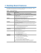
1 Desktop Board Features This chapter briefly describes the features of Intel® Desktop Board DG33FB. Table 1 summarizes the major features of the Desktop Board. Table 1. Feature Summary Form Factor ATX (320.04 millimeters [11.60 inches] x 243.84 millimeters [9.60 inches]) Processor Support for an Intel® processor in the LGA775 package Main Memory • Four 240-pin, DDR2 1.
Intel Desktop Board DG33FB Product Guide Table 1.
Desktop Board Features Desktop Board Components Figure 1 shows the approximate location of the major components on Desktop Board DG33FB. Figure 1.
Intel Desktop Board DG33FB Product Guide Table 2.
Desktop Board Features Processor CAUTION Failure to use an appropriate power supply and/or not connecting the 12 V (2 x 2 pin) power connector to the Desktop Board may result in damage to the board, or the system may not function properly. Desktop Board DG33FB supports an Intel processor in the LGA775 package. Processors are not included with the Desktop Board and must be purchased separately. The processor connects to the Desktop Board through the LGA775 socket.
Intel Desktop Board DG33FB Product Guide ⎯ Memory configurations listed below: • Up to 2.0 GB utilizing 256 Mb technology • Up to 4.0 GB utilizing 512 Mb or 1 Gb technology • Up to 8.0 GB utilizing 1 Gb technology Related Links: Go to the following links or pages for more information about: • • • • SDRAM specifications, http://www.intel.com/technology/memory/ Installing memory, page 34 in Chapter 2 Tested memory, http://www.cmtlabs.com/mbsearch.asp or http://www.intel.com/products/motherboard/index.
Desktop Board Features • 3D Graphics Rendering enhancements: ⎯ 1.6 dual texture GigaPixel/s maximum fill rate ⎯ 16-bit and 32-bit color ⎯ Maximum 3D supported resolution of 1600 x 1200 x 32 at 85 Hz • ⎯ Vertex cache Video ⎯ Software DVD at 30 fps full screen ⎯ Adaptive deinterlacing • ⎯ Dynamic Video Memory Technology (DVMT) support up to 256 MB Display ⎯ Intel TV Wizard utility (step-by-step setup help for TVs and displays) ⎯ Up to 2048 x 1536 at 75 Hz refresh (QXGA) ⎯ DVI specification 1.
Intel Desktop Board DG33FB Product Guide Audio Subsystem The onboard audio subsystem consists of the following: • • • • Intel ICH9DH I/O controller hub RealTek ALC888 audio codec Back panel audio connectors Intel High Definition audio front panel audio header The audio subsystem supports the following features: • • A signal-to-noise (S/N) ratio of 95 dB Independent multi-streaming 5.1 audio (using the back panel audio connectors) and stereo (using the Intel High Definition front panel audio header).
Desktop Board Features RJ-45 LAN Connector LEDs Two LEDs are built into the RJ-45 LAN connector located on the back panel (see Figure 2). These LEDs indicate the status of the LAN. Figure 2. LAN Connector LEDs Table 3 describes the LED states when the board is powered up and the LAN subsystem is operating. Table 3.
Intel Desktop Board DG33FB Product Guide Hi-Speed USB 2.0 Support The Desktop Board supports up to 12 USB 2.0 ports (six ports routed to the back panel and six ports routed to three internal headers) via the ICH9DH. USB 2.0 ports are backward compatible with USB 1.1 devices. USB 1.1 devices will function normally at USB 1.1 speeds. USB 2.0 support requires both an operating system and drivers that fully support USB 2.0 transfer rates. Disabling Hi-Speed USB in the BIOS reverts all USB 2.0 ports to USB 1.
Desktop Board Features Serial ATA and IDE Auto Configuration If you install a Serial ATA or IDE device (such as a hard drive) in your computer, the auto-configuration utility in the BIOS automatically detects and configures the device for your computer. You do not need to run the BIOS Setup program after installing a Serial ATA or IDE device. You can override the auto-configuration options by specifying manual configuration in the BIOS Setup program.
Intel Desktop Board DG33FB Product Guide Hardware Monitoring and Fan Speed Control The features of the hardware monitoring and fan speed control include: • • Monitoring of power supply voltages to detect levels above and below acceptable values Intel Quiet System Technology fan speed control, delivering acoustically-optimized thermal management NOTE Memory must be installed in the Channel A, DIMM 0 socket to enable Intel Quiet System Technology.
Desktop Board Features Hardware Support Power Connectors ATX12V-compliant power supplies can turn off the computer power through system control. When an ACPI-enabled computer receives the correct command, the power supply removes all non-standby voltages. When resuming from an AC power failure, the computer returns to the power state it was in before power was interrupted (either on or off). The computer’s response can be set by using the Last Power State feature in the BIOS Setup program’s Boot menu.
Intel Desktop Board DG33FB Product Guide Instantly Available PC Technology CAUTIONS For Instantly Available PC technology, the 5 V standby line for the power supply must be capable of delivering adequate +5 V standby current. Failure to provide adequate standby current when using this feature can damage the power supply and/or effect ACPI S3 sleep state functionality.
Desktop Board Features Figure 3. Location of the Standby Power Indicator Related Links: For more information on standby current requirements for the Desktop Board, refer to the Technical Product Specification by going to the following link, finding the product, and selecting Product Documentation from the left-hand menu: http://support.intel.com/support/motherboards/desktop/ Wake from USB NOTE Wake from USB requires the use of a USB peripheral that supports Wake from USB.
Intel Desktop Board DG33FB Product Guide ENERGY STAR* Qualified In 2007, the US Department of Energy and the US Environmental Protection Agency revised the ENERGY STAR requirements. Intel worked directly with these two governmental agencies to define the new requirements. Currently Intel Desktop Boards meet the new ENERGY STAR requirements. For information about the ENERGY STAR specifications, see: http://www3.intel.com/cd/channel/reseller/asmo-na/eng/337748.htm.
2 Installing and Replacing Desktop Board Components This chapter tells you how to: • • • • • • • • • • • • • Install the I/O shield Install and remove the Desktop Board Install and remove a processor Install and remove memory Install and remove a PCI Express x16 card Connet the diskette drive cable Connect the IDE and Serial ATA cables Connect to the internal headers Connect to the flexible audio system Connect chassis fan and power supply cables Set the BIOS configuration jumper Clear passwords Replace th
Intel Desktop Board DG33FB Product Guide Installation Precautions When you install and test the Intel Desktop Board, observe all warnings and cautions in the installation instructions.
Installing and Replacing Desktop Board Components Installing the I/O Shield The Desktop Board comes with an I/O shield. When installed in the chassis, the shield blocks radio frequency transmissions, protects internal components from dust and foreign objects, and promotes correct airflow within the chassis. Install the I/O shield before installing the Desktop Board in the chassis. Place the shield inside the chassis as shown in Figure 4. Press the shield into place so that it fits tightly and securely.
Intel Desktop Board DG33FB Product Guide Installing and Removing the Desktop Board CAUTION Only qualified technical personnel should do this procedure. Disconnect the computer from its power source before performing the procedures described here. Failure to disconnect the power before you open the computer can result in personal injury or equipment damage. Refer to your chassis manual for instructions on installing and removing the Desktop Board.
Installing and Replacing Desktop Board Components Installing and Removing a Processor Instructions on how to install the processor to the Desktop Board are given below. Installing a Processor CAUTION Before installing or removing the processor, make sure the AC power has been removed by unplugging the power cord from the computer; the standby power LED should not be lit (see Figure 3 on page 23). Failure to do so could damage the processor and the board.
Intel Desktop Board DG33FB Product Guide 3. Lift the load plate (Figure 7, A). Do not touch the socket contacts (Figure 7, B). Figure 7. Lift the Load Plate 4. Remove the plastic protective socket cover from the load plate (Figure 8). Do not discard the protective socket cover. Always replace the socket cover if the processor is removed from the socket. Figure 8.
Installing and Replacing Desktop Board Components 5. Remove the processor from the protective processor cover. Hold the processor only at the edges, being careful not to touch the bottom of the processor (see Figure 9). Do not discard the protective processor cover. Always replace the processor cover if the processor is removed from the socket. Figure 9. Remove the Processor from the Protective Processor Cover 6. Hold the processor with your thumb and index fingers oriented as shown in Figure 10.
Intel Desktop Board DG33FB Product Guide 7. Pressing down on the load plate (Figure 11, A), close and engage the socket lever (Figure 11, B). Figure 11. Close the Load Plate Installing the Processor Fan Heat Sink Desktop Board DG33FB has mounting holes for a processor fan heat sink. For instructions on how to attach the processor fan heat sink to the Desktop Board, refer to the boxed processor manual.
Installing and Replacing Desktop Board Components Connecting the Processor Fan Heat Sink Cable Connect the processor fan heat sink cable to the 4-pin processor fan header (see Figure 12). A fan with a 4-pin connector as shown in Figure 12, A is recommended; however, a fan with a 3-pin connector (Figure 12, B) can be used. However, since a fan with a 3-pin connector cannot use the onboard fan control, the fan will always operate at full speed. Figure 12.
Intel Desktop Board DG33FB Product Guide Removing the Processor For instructions on how to remove the processor fan heat sink and processor, refer to the processor installation manual. Installing and Removing Memory NOTE To be fully compliant with all applicable Intel SDRAM memory specifications, the board requires DIMMs that support the Serial Presence Detect (SPD) data structure. Desktop board DG33FB has four 240-pin DDR2 DIMM sockets arranged as DIMM 0 and DIMM 1 in both Channel A and Channel B.
Installing and Replacing Desktop Board Components If additional memory is to be used, install another matched pair of DIMMs in DIMM 1 (black) in channels A and B (see Figure 14). Figure 14. Dual Channel Memory Configuration with Four DIMMs Three DIMMs If you want to use three DIMMs in a dual-channel configuration, install a matched pair of DIMMs equal in speed and size in DIMM 0 (blue) and DIMM 1 (black) of channel A.
Intel Desktop Board DG33FB Product Guide Installing DIMMs To make sure you have the correct DIMM, place it on the illustration of the DDR2 DIMM in Figure 16. All the notches should match with the DDR2 DIMM. Figure 16.
Installing and Replacing Desktop Board Components NOTE Memory must be installed in the Channel A, DIMM 0 socket to enable Intel Quiet System Technology. To install a DIMM, follow these steps: 1. Observe the precautions in "Before You Begin" on page 25. 2. Turn off all peripheral devices connected to the computer. Turn off the computer and disconnect the AC power cord. 3. Remove the computer’s cover and locate the DIMM sockets (see Figure 17). Figure 17. Installing a DIMM 4.
Intel Desktop Board DG33FB Product Guide 7. Insert the bottom edge of the DIMM into the socket. 8. When the DIMM is inserted, push down on the top edge of the DIMM until the retaining clips snap into place. Make sure the clips are firmly in place. 9. Replace the computer’s cover and reconnect the AC power cord. Removing DIMMs To remove a DIMM, follow these steps: Observe the precautions in "Before You Begin" on page 25. Turn off all peripheral devices connected to the computer. Turn off the computer.
Installing and Replacing Desktop Board Components Installing and Removing a PCI Express x16 Card CAUTION When installing a PCI Express x16 card on the Desktop Board, ensure that the card is fully seated in the PCI Express x16 connector before you power on the system. If the card is not fully seated in the PCI Express connector, an electrical short may result across the PCI Express connector pins.
Intel Desktop Board DG33FB Product Guide Removing the PCI Express x16 Card Follow these instructions to remove the PCI Express x16 card from the connector: 1. Observe the precautions in "Before You Begin" on page 25. 2. Remove the screw (Figure 19, A) that secures the card’s metal bracket to the chassis back panel. 3. Push the card ejector lever down using the tip of a pencil or similar tool (Figure 19, B) in the notch. This will release the card from the connector (C). 4. Pull the card straight up.
Installing and Replacing Desktop Board Components Connecting the Diskette Drive Cable The diskette drive cable can be used to connect a single diskette drive to the Desktop Board. For correct function of the cable: • • • Observe the precautions in "Before You Begin" on page 25. Attach the cable end labeled P1 to the diskette drive connector on the Intel Desktop Board (Figure 20, A). Attach the cable end labeled P2 to the diskette drive (Figure 20, B). Figure 20.
Intel Desktop Board DG33FB Product Guide Connecting the IDE Cable The IDE cable can be used to connect two IDE drives to the Desktop Board. The cable supports the ATA-66/100 transfer protocol. Figure 21 shows the correct installation of the cable. NOTES ATA-66/100 compatible cables are backward compatible with drives using slower IDE transfer protocols.
Installing and Replacing Desktop Board Components Figure 21.
Intel Desktop Board DG33FB Product Guide Connecting the Serial ATA (SATA) Cables SATA cables support the Serial ATA protocol. Each cable can be used to connect a single SATA drive to the Desktop Board. For correct cable function: 1. Observe the precautions in "Before You Begin" on page 25. 2. Attach one end of the SATA cable to one of the SATA connectors on the board (Figure 22, A). 3. Attach the other end of the SATA cable to the SATA drive (Figure 22, B). Figure 22.
Installing and Replacing Desktop Board Components Connecting to the Internal Headers Before connecting cables to the internal headers, observe the precautions in “Before You Begin” on page 25. Figure 23 shows the location of the internal headers. Item A B C D Description IEEE 1394a Front panel audio Serial port Chassis Intrusion Item E F G Description Alternate front panel power LED Front panel USB 2.0 Figure 23.
Intel Desktop Board DG33FB Product Guide Connecting to the IEEE 1394a Header See Figure 23, A for the location of the IEEE 1394a header. Table 4 shows the pin assignments for the header. Table 4. IEEE 1394a Signal Header Names Pin Signal Name Pin Signal Name 1 TPA1+ 2 TPA1- 3 Ground 4 Ground 5 TPA2+ 6 TPA2- 7 +12 V 8 +12 V 9 Key (no pin) 10 Ground Installing a Front Panel Audio Solution for Intel® High Definition Audio Figure 23, B shows the location of the front panel audio header.
Installing and Replacing Desktop Board Components Connecting to the Serial Port Header See Figure 23, C for the location of the serial port header. Table 6 shows the pin assignments for the header. Table 6. Serial Port Header Signal Names Pin Signal Name Pin Signal Name 1 DCD 2 RXD# 3 TXD# 4 DTR 5 Ground 6 DSR 7 RTS 8 CTS 9 RI 10 No Connection Connecting to the Chassis Intrusion Header Figure 23, D on page 45 shows the location of the chassis intrusion header.
Intel Desktop Board DG33FB Product Guide Connecting to the Front Panel Header Before connecting to the front panel header, observe the precautions in "Before You Begin" on page 25. See Figure 23, F for the location of the multi-colored front panel header. Table 9 shows the pin assignments for the front panel header. Table 9.
Installing and Replacing Desktop Board Components Connecting to the Flexible Audio System After installing the RealTek audio driver from the Intel Express Installer CD-ROM, the multi-channel audio feature can be enabled. Figure 24 shows the back panel audio connectors. The default connector assignments are shown in the table. Item Description A Line In B Line Out C Mic In Figure 24.
Intel Desktop Board DG33FB Product Guide Connecting Chassis Fan and Power Supply Cables Connecting Chassis Fan Cables Connect chassis fan cables to the 3-pin and 4-pin chassis fan headers on the Desktop Board. Figure 25 shows the location of the chassis fan headers. Figure 25.
Installing and Replacing Desktop Board Components Connecting Power Supply Cables CAUTION Failure to use an appropriate power supply and/or not connecting the 12 V (2 x 2 pin) power connector to the Desktop Board may result in damage to the board or the system may not function properly. The 2 x 12 pin main power connector on the Desktop Board is backwards compatible with ATX12V power supplies with 2 x 10 connectors. Figure 26 shows the location of the Desktop Board power connectors. Figure 26.
Intel Desktop Board DG33FB Product Guide Setting the BIOS Configuration Jumper NOTE Always turn off the power and unplug the power cord from the computer before moving the jumper. Moving the jumper with the power on may result in unreliable computer operation. Figure 27 shows the location of the Desktop Board’s BIOS configuration jumper block. Figure 27. Location of the BIOS Configuration Jumper Block The three-pin BIOS jumper block enables all board configurations to be done in the BIOS Setup program.
Installing and Replacing Desktop Board Components Table 11. Jumper Settings for the BIOS Setup Program Modes Jumper Setting Mode Description Normal (default) (1-2) The BIOS uses the current configuration and passwords for booting. Configure (2-3) After the Power-On Self-Test (POST) runs, the BIOS displays the Maintenance Menu. Use this menu to clear passwords. Recovery (None) The BIOS recovers data in the event of a failed BIOS update.
Intel Desktop Board DG33FB Product Guide 10. Turn off the computer. Disconnect the computer’s power cord from the AC power source. 11. Remove the computer cover. 12. To restore normal operation, place the jumper on pins 1-2 as shown below. 13. Replace the cover, plug in the computer, and turn on the computer. Replacing the Battery A coin-cell battery (CR2032) powers the real-time clock and CMOS memory. When the computer is not plugged into a wall socket, the battery has an estimated life of three years.
Installing and Replacing Desktop Board Components VIKTIGT! Risk för explosion om batteriet ersätts med felaktig batterityp. Batterier ska kasseras enligt de lokala miljövårdsbestämmelserna. VARO Räjähdysvaara, jos pariston tyyppi on väärä. Paristot on kierrätettävä, jos se on mahdollista. Käytetyt paristot on hävitettävä paikallisten ympäristömääräysten mukaisesti. VORSICHT Bei falschem Einsetzen einer neuen Batterie besteht Explosionsgefahr.
Intel Desktop Board DG33FB Product Guide Προσοχή Υπάρχει κίνδυνος για έκρηξη σε περίπτωση που η μπαταρία αντικατασταθεί από μία λανθασμένου τύπου. Οι μπαταρίες θα πρέπει να ανακυκλώνονται όταν κάτι τέτοιο είναι δυνατό. Η απόρριψη των χρησιμοποιημένων μπαταριών πρέπει να γίνεται σύμφωνα με τους κατά τόπο περιβαλλοντικούς κανονισμούς. VIGYAZAT Ha a telepet nem a megfelelő típusú telepre cseréli, az felrobbanhat. A telepeket lehetőség szerint újra kell hasznosítani.
Installing and Replacing Desktop Board Components POZOR Zamenjava baterije z baterijo drugačnega tipa lahko povzroči eksplozijo. Če je mogoče, baterije reciklirajte. Rabljene baterije zavrzite v skladu z lokalnimi okoljevarstvenimi predpisi. . UYARI Yanlış türde pil takıldığında patlama riski vardır. Piller mümkün olduğunda geri dönüştürülmelidir. Kullanılmış piller, yerel çevre yasalarına uygun olarak atılmalıdır. OСТОРОГА Використовуйте батареї правильного типу, інакше існуватиме ризик вибуху.
Intel Desktop Board DG33FB Product Guide To replace the battery, follow these steps: 1. Observe the precautions in "Before You Begin" (see page 25). 2. Turn off all peripheral devices connected to the computer. Disconnect the computer’s power cord from the AC power source (wall outlet or power adapter). 3. Remove the computer cover. 4. Locate the battery on the board (see Figure 28). 5. With a medium flat-bladed screwdriver, gently pry the battery free from its connector.
3 Updating the BIOS The BIOS Setup program can be used to view and change the BIOS settings for the computer. You can access the BIOS Setup program by pressing the key after the Power-On Self-Test (POST) memory test begins and before the operating system boot begins. This chapter tells you how to update the BIOS by either using the Intel Express BIOS Update utility or the Iflash Memory Update utility, and how to recover the BIOS if an update fails.
Intel Desktop Board DG33FB Product Guide Updating the BIOS with the ISO Image BIOS Update File or the Iflash Memory Update Utility You can use the information in this section to update the BIOS using either the Iflash Memory Update Utility or the ISO Image BIOS update file. Obtaining the BIOS Update File You can update to a new version of the BIOS by using the ISO Image BIOS update file (recommended), or Iflash BIOS update file.
Updating the BIOS CAUTION Do not interrupt the process or the system may not function properly. Follow these instructions to upgrade the BIOS using the ISO Image BIOS file: 1. Download the ISO Image BIOS file. 2. Using software capable of uncompressing and writing an ISO image file to CD, burn the data to a blank CD. NOTE Copying the ISO Image BIOS file to CD will not work. The completed CD should contain multiple files and a directory. 3.
Intel Desktop Board DG33FB Product Guide CAUTION Do not interrupt the process or the system may not function properly. 1. Uncompress the BIOS update file and copy the .BIO file, IFLASH.EXE, and .ITK file (optional) to a bootable USB flash drive or other bootable USB media. 2. Configure the BIOS or use the F10 option during POST to boot to the USB device. 3. Manually run the IFLASH.EXE file from the USB device and manually update the BIOS.
A Error Messages and Indicators Desktop Board DG33FB reports POST errors in two ways: • • By sounding a beep code By displaying an error message on the monitor BIOS Beep Codes The BIOS also issues a beep code (one long tone followed by two short tones) during POST if the video configuration fails (a faulty video card or no card installed) or if an external ROM module does not properly checksum to zero. Table 12 lists the BIOS codes. Table 12.
Intel Desktop Board DG33FB Product Guide 64
B Regulatory Compliance This appendix contains the following regulatory compliance information for Desktop Board DG33FB: • • • • • Safety regulations European Union Declaration of Conformity statement Product Ecology statements Electromagnetic Compatibility (EMC) regulations Product certifications Safety Regulations Desktop Board DG33FB complies with the safety regulations stated in Table 14 when correctly installed in a compatible host system. Table 14.
Intel Desktop Board DG33FB Product Guide European Union Declaration of Conformity Statement We, Intel Corporation, declare under our sole responsibility that the product Intel® Desktop Board DG33FB is in conformity with all applicable essential requirements necessary for CE marking, following the provisions of the European Council Directive 89/336/EEC (EMC Directive) and Council Directive 73/23/EEC (Safety/Low Voltage Directive).
Regulatory Compliance Lietuvių Šis produktas atitinka Europos direktyvų 89/336/EEC ir 73/23/EEC nuostatas. Malti Dan il-prodott hu konformi mal-provvedimenti tad-Direttivi Ewropej 89/336/EEC u 73/23/EEC. Norsk Dette produktet er i henhold til bestemmelsene i det europeiske direktivet 89/336/ EEC & 73/23/EEC. Polski Niniejszy produkt jest zgodny z postanowieniami Dyrektyw Unii Europejskiej 89/336/EWG i 73/23/EWG. Portuguese Este produto cumpre com as normas da Diretiva Européia 89/336/EEC & 73/23/EEC.
Intel Desktop Board DG33FB Product Guide Product Ecology Statements The following information is provided to address worldwide product ecology concerns and regulations. Recycling Considerations As part of its commitment to environmental responsibility, Intel has implemented the Intel® Product Recycling Program to allow retail consumers of Intel’s branded products to return used products to select locations for proper recycling. Please consult http://www.intel.
Regulatory Compliance Français Dans le cadre de son engagement pour la protection de l'environnement, Intel a mis en œuvre le programme Intel Product Recycling Program (Programme de recyclage des produits Intel) pour permettre aux consommateurs de produits Intel de recycler les produits usés en les retournant à des adresses spécifiées. Visitez la page Webhttp://www.intel.
Intel Desktop Board DG33FB Product Guide Türkçe Intel, çevre sorumluluğuna bağımlılığının bir parçası olarak, perakende tüketicilerin Intel markalı kullanılmış ürünlerini belirlenmiş merkezlere iade edip uygun şekilde geri dönüştürmesini amaçlayan Intel Ürünleri Geri Dönüşüm Programı’nı uygulamaya koymuştur. Bu programın ürün kapsamı, ürün iade merkezleri, nakliye talimatları, kayıtlar ve şartlar v.s dahil bütün ayrıntılarını ögrenmek için lütfen http://www.intel.
Regulatory Compliance Table 15. Lead-Free Board Markings Description Mark nd Lead-Free 2 Level Interconnect: This symbol is used to identify electrical and electronic assemblies and components in which the lead (Pb) concentration level in the Desktop Board substrate and the solder connections from the board to the components (second-level interconnect) is not greater than 0.1% by weight (1000 ppm).
Intel Desktop Board DG33FB Product Guide EMC Regulations Desktop Board DG33FB complies with the EMC regulations stated in Table 16 when correctly installed in a compatible host system. Table 16. EMC Regulations Regulation Title FCC Class B Title 47 of the Code of Federal Regulations, Parts 2 and 15, Subpart B, Radio Frequency Devices. (USA) ICES-003 (Class B) Interference-Causing Equipment Standard, Digital Apparatus.
Regulatory Compliance Korean Class B statement translation: This is household equipment that is certified to comply with EMC requirements. You may use this equipment in residential environments and other non-residential environments. Ensure Electromagnetic Compatibility (EMC) Compliance Before computer integration, make sure that the power supply and other modules or peripherals, as applicable, have passed Class B EMC testing and are marked accordingly.
Intel Desktop Board DG33FB Product Guide Product Certifications Board-Level Certification Markings Desktop Board DG33FB has the following product certification markings: Table 17. Product Certification Markings Description Mark UL joint US/Canada Recognized Component mark. Includes adjacent UL file number for Intel Desktop Boards: E210882. FCC Declaration of Conformity logo mark for Class B equipment. Includes Intel name and DG33FB model designation. CE mark.
Regulatory Compliance Chassis and Component Certifications Ensure that the chassis and certain components; such as the power supply, peripheral drives, wiring, and cables; are components certified for the country or market where used. Agency certification marks on the product are proof of certification. Typical product certifications include: In Europe The CE marking signifies compliance with all applicable European requirements.