
Intel Desktop Board DG31PR Technical Product Specification

Intel Desktop Board DG31PR Technical Product Specification
48
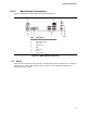
2.2.2.3 Auxiliary Front Panel Power/Sleep LED Header
Pins 1 and 3 of this header duplicate the signals on pins 2 and 4 of the front panel
header.
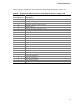
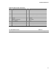
Table 17. Auxiliary Front Panel Power/Sleep LED Header
Pin Signal Name In/Out Description
1 HDR_BLNK_GRN Out Front panel green LED
2 Not connected
3 HDR_BLNK_YEL Out Front panel yellow LED
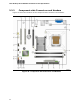
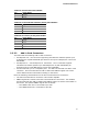
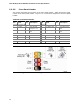
2.2.2.4 Power Supply Connectors
The board has the following power supply connectors:
• Main power – a 2 x 12 connector. This connector is compatible with 2 x 10
connectors previously used on Intel Desktop boards. The board supports the use
of ATX12V power supplies with either 2 x 10 or 2 x 12 main power cables. When
using a power supply with a 2 x 10 main power cable, attach that cable on the
rightmost pins of the main power connector, leaving pins 11, 12, 23, and 24
unconnected.
• Processor core power – a 2 x 2 connector. This connector provides power
directly to the processor voltage regulator and must always be used. Failure to do
so will prevent the board from booting.
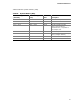
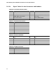
Table 18. Processor Core Power Connector
Pin Signal Name Pin Signal Name
1 Ground 2 Ground
3 +12 V 4 +12 V