
Intel Desktop Board DG31PR Technical Product Specification

Product Description
21
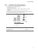
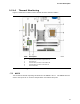
1.6.2 USB
The board supports up to eight USB 2.0 ports, supports UHCI and EHCI, and uses
UHCI- and EHCI-compatible drivers.
The ICH7 provides the USB controller for all ports. The port arrangement is as
follows:
• Four ports are implemented with stacked back panel connectors
• Four ports are routed to two separate front panel USB headers
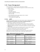
For information about Refer to
The location of the USB connectors on the back panel Figure 9, page 43
The location of the front panel USB headers Figure 10, page 44
1.6.3 IDE Support
The board provides five IDE interface connectors:
• One parallel ATA IDE connector that supports two devices
• Four serial ATA IDE connectors that support one device per connector
1.6.3.1 Parallel ATE IDE Interface
The ICH7’s Parallel ATA IDE controller has one bus-mastering Parallel ATA IDE
interface. The Parallel ATA IDE interface supports the following modes:
• Programmed I/O (PIO): processor controls data transfer.
• 8237-style DMA: DMA offloads the processor, supporting transfer rates of up to
16 MB/sec.
• Ultra DMA: DMA protocol on IDE bus supporting host and target throttling and
transfer rates of up to 33 MB/sec.
• ATA-66: DMA protocol on IDE bus supporting host and target throttling and
transfer rates of up to 66 MB/sec. ATA-66 protocol is similar to Ultra DMA and is
device driver compatible.
• ATA-100: DMA protocol on IDE bus allows host and target throttling. The ICH7’s
ATA-100 logic can achieve read transfer rates up to 100 MB/sec and write transfer
rates up to 88 MB/sec.
NOTE
ATA-66 and ATA-100 are faster timings and require a specialized cable to reduce
reflections, noise, and inductive coupling.
The Parallel ATA IDE interface also supports ATAPI devices (such as CD-ROM drives)
and ATA devices using the transfer modes.
The BIOS supports Logical Block Addressing (LBA) and Extended Cylinder Head Sector
(ECHS) translation modes. The drive reports the transfer rate and translation mode to
the BIOS.
For information about Refer to
The location of the Parallel ATA IDE connector
Figure 10, page 44